
Glass Damage Risk From Solar Clamping: How to Protect Frameless PV Modules
Frameless solar modules require a more carefully controlled mounting interface than conventional framed modules. The clamp must retain the module without creating an unapproved contact condition, excessive local pressure, glass damage or laminate damage.
The key rule is straightforward: do not assume that a clamp is suitable for a frameless module simply because it fits the module edge or includes a rubber pad. The mounting method, contact geometry, clamp position and hardware arrangement must follow the module manufacturer’s instructions or an approved mounting configuration.
A compliant layer such as EPDM can form part of the interface, but it does not make an otherwise unsuitable clamp safe.
1. How can solar clamping damage a frameless module?
A frameless module does not have the conventional aluminum frame that provides a defined structural clamping interface. Depending on the module design, the mounting clamp may interact with the glass surfaces, glass edge or a manufacturer-defined perimeter region.
Potential damage mechanisms include:
Direct contact damage: a metal clamp or another hard component contacts a glass surface where direct contact is not permitted.
Local contact pressure: a small or uneven contact area creates concentrated pressure at the interface.
Edge damage: an unsuitable clamp shape, alignment or installation condition causes local contact or chipping near the glass edge.
Excessive deformation: the clamp arrangement imposes a mechanical condition outside the module’s qualified mounting method.
Surface damage: rough, burred or contaminated contact surfaces scratch or damage the interface.
Movement or slipping: inadequate retention allows relative movement, potentially changing the contact condition during service.
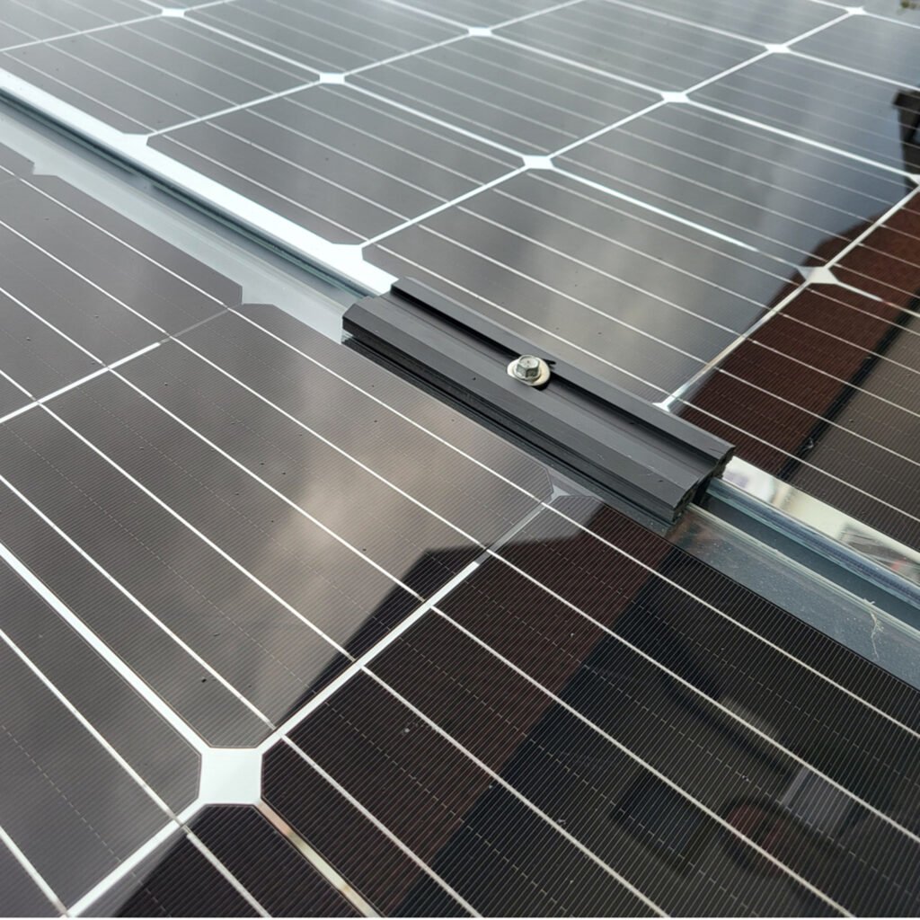
These are risk mechanisms to assess, not a claim that every instance of metal contact or every installation error will cause a glass fracture. The actual outcome depends on the module construction, contact geometry, loading and installation condition.
2. The clamp-to-glass interface is the first point to check
The clamp contact surface should be compatible with the mounting method specified by the module manufacturer.
For a frameless module, check the following before selecting a clamp:
Direct metal-to-glass contact
Do not assume direct metal-to-glass contact is acceptable.
JA Solar’s 2018 PV Module Installation Manual for frameless double-glass modules states that clamps must not contact the glass directly or deform and damage it. It also calls for a rubber washer and a smooth clamp contact area. This is a manufacturer-specific instruction for the module configurations covered by that manual, not a universal specification for every frameless module.
The practical implication is that the contact arrangement must be confirmed against the exact module manual. A clamp drawing alone cannot establish that the interface is approved.
Contact surface condition
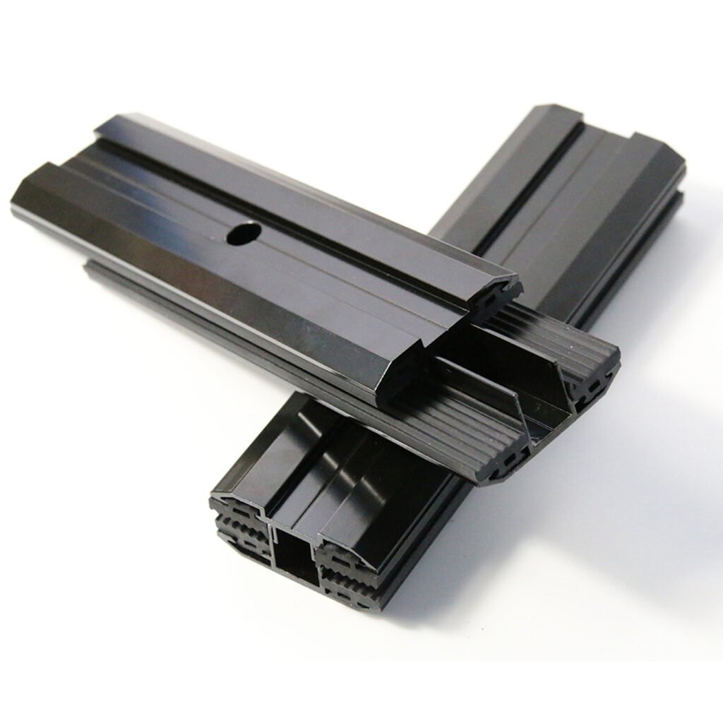
Inspect the clamp surfaces that may contact the module or its interface layer.
Check for:
sharp edges or burrs;
rough or damaged surfaces;
protruding fasteners;
uneven contact faces;
contamination or embedded metal particles;
inconsistent surface finish.
A smooth contact surface reduces the risk of damaging the interface, but surface finish alone does not qualify the clamp. The contact geometry and complete assembly still need to comply with the module manufacturer’s requirements.
Contact area and geometry
A clamp with a larger contact area is not automatically safer. Its shape, position, overlap, support and pressure distribution must be suitable for the module.
Do not increase clamp width, length or overlap as an improvised way to reduce pressure. A dimensional change can alter the mounting arrangement and may require renewed compatibility assessment.
3. EPDM is an interface component, not a guarantee against glass damage
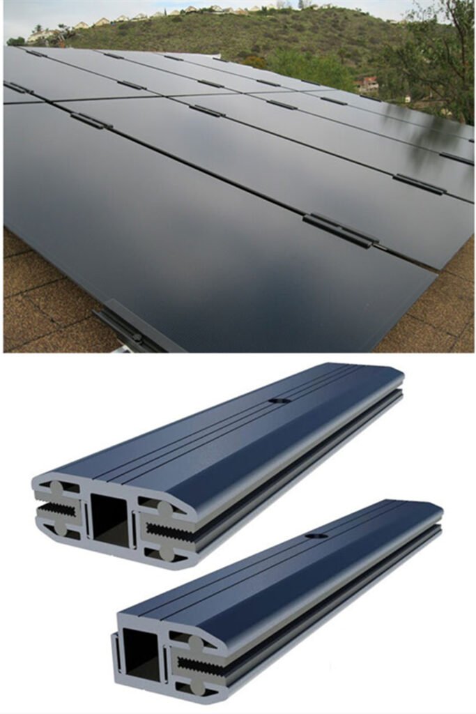
EPDM rubber is used in some frameless module clamp arrangements as a compliant interface layer.
Its purpose and performance depend on the specified material and the way it is incorporated into the clamp assembly.
Important variables include:
material type and specification;
thickness;
hardness and compression behavior;
contact width and shape;
retention within the clamp;
resistance to displacement during installation and service;
compatibility with the module’s glass and edge construction;
environmental durability.
JA Solar’s 2018 manual identifies an EPDM rubber interface in its illustrated frameless double-glass clamp arrangement. The manual also requires the clamp contact area to be smooth and prohibits direct clamp contact with the glass.
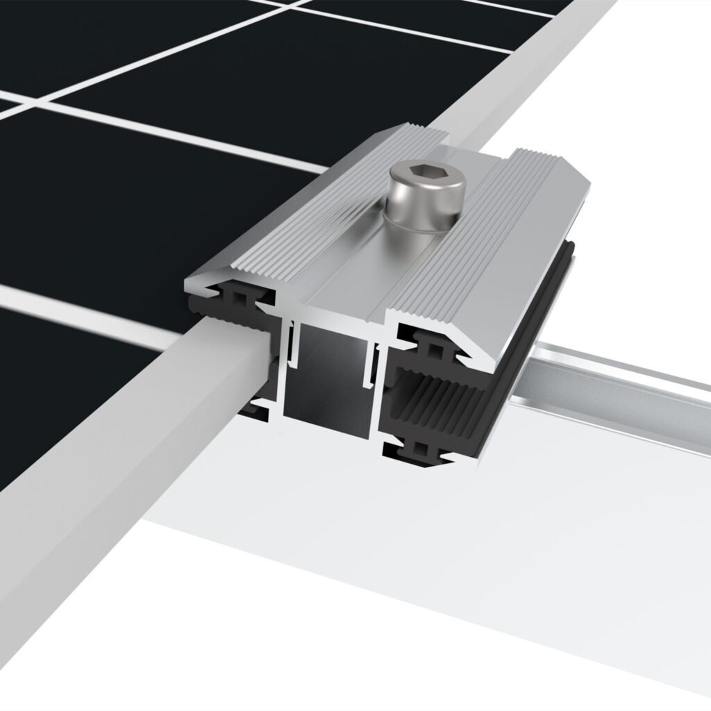
This is useful evidence that the rubber layer is part of a defined mounting configuration. It does not establish that any EPDM strip, regardless of thickness, hardness or geometry, is suitable.
Do not treat EPDM as a universal protective solution. An incorrectly sized, displaced, damaged or unqualified pad may fail to provide the intended interface.
For a custom clamp, the rubber material and dimensions should be specified and reviewed as part of the complete clamp design—not selected only by appearance or nominal thickness.
4. Clamp position and overlap must follow the module requirements
The clamp’s position is a structural and compatibility issue, not merely an installation preference.
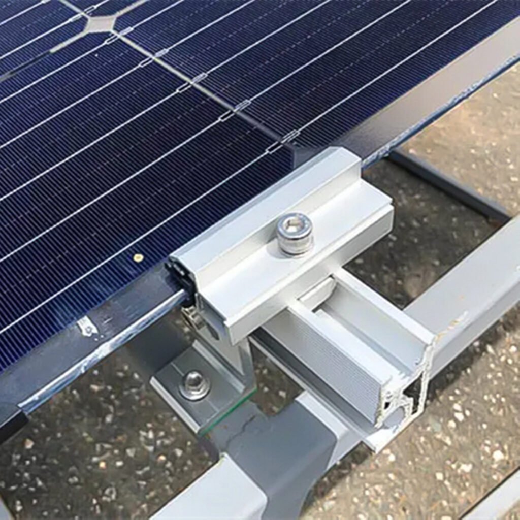
For frameless modules, the permitted mounting zone and clamp geometry should be confirmed from the module manufacturer’s documentation.
Check:
The approved clamping or mounting zone.
The permitted clamp position relative to the module edge.
The required overlap and contact geometry.
The number and location of clamps.
The required support arrangement.
Whether the arrangement differs between portrait and landscape installation.
Whether the module has separate requirements for monofacial and bifacial configurations.
Do not copy overlap dimensions from another module brand or model.
For example, JA Solar‘s manual describes a dedicated clamp arrangement for the frameless modules covered by that document. Its dimensions and installation details should not be transferred to a different module without approval.
The same principle applies to clamp position: a clamp that physically fits may still be outside the module’s approved mounting zone.
5. Installation errors that increase the risk
Even a suitable clamp can be installed incorrectly.
The following conditions should be checked during installation:
| Installation condition | Why it matters | What to verify |
|---|---|---|
| Clamp is misaligned | Contact may become uneven or fall outside the permitted zone | Position against the module installation drawing |
| Rubber pad is missing or displaced | The intended interface may no longer exist | Correct material, position and retention |
| Clamp surface has burrs or damage | Local contact or surface damage may occur | Inspect contact faces before installation |
| Fastener is overtightened | The assembly may be loaded beyond its specified installation condition | Use the torque and sequence specified for the exact system |
| Clamp geometry is modified on site | The qualified interface may have changed | Obtain manufacturer or engineering approval |
| Module is forced into position | Unintended contact or installation stress may be introduced | Correct rail alignment and support before tightening |
There is no universal torque value for all frameless clamps. The correct value depends on the defined clamp, fastener, module and mounting system.
Do not use a torque value from another module manual simply because the bolt size is the same.
6. How to assess a frameless clamp before ordering
A supplier should not confirm compatibility based only on module thickness or a photograph of the module edge.
A proper review should cover three connected areas.
A. Module information
Request:
module manufacturer and exact model;
current module installation manual;
module construction and glass specification;
approved mounting method;
permitted clamp zones and relevant dimensional drawings;
manufacturer confirmation where the proposed arrangement is not explicitly covered.
B. Clamp information
Request:
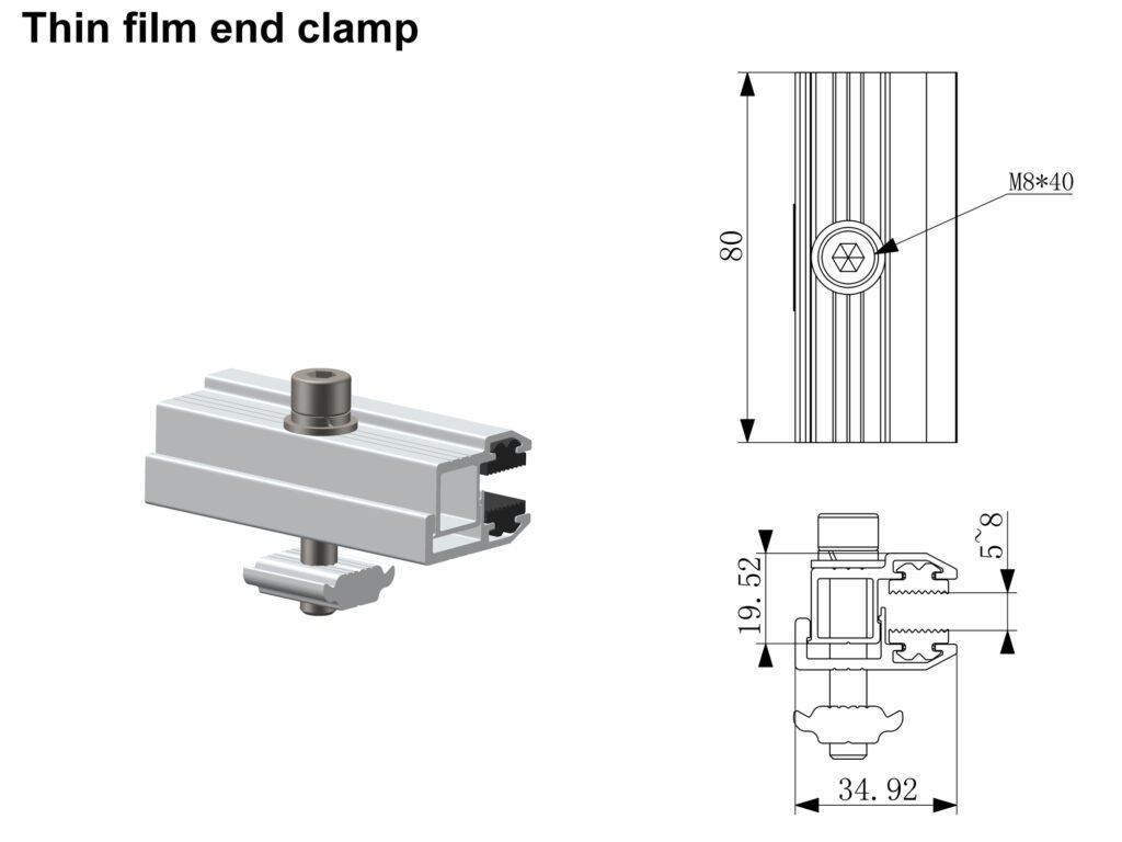
clamp drawings with dimensions and tolerances;
material and surface-finish information;
contact-face geometry;
EPDM or other interface material specification;
fastener and rail-interface details;
installation instructions, including the applicable torque and sequence.
C. Complete mounting arrangement
Review the clamp together with:
the module;
the rail and its support geometry;
the fastener arrangement;
the number and position of clamps;
the intended installation orientation;
the relevant project load conditions.
A clamp cannot be qualified independently of the module and the rest of the mounting arrangement.
7. What evidence should a buyer request?
Before approving a frameless clamp for a project, request evidence that addresses the actual module and mounting configuration.
| Evidence | What it should establish |
|---|---|
| Module installation manual | Approved mounting method, mounting zone and module-specific limitations |
| Clamp technical drawing | Contact geometry, dimensions and tolerances |
| Interface material specification | Material identity and relevant properties of the rubber layer |
| Assembly drawing | How the clamp, module, rail and fasteners are arranged |
| Installation instructions | Correct positioning, sequence and system-specific torque |
| Compatibility approval | Whether the proposed clamp arrangement is accepted for the exact module |
| Test or engineering evidence, where required | Performance of the defined assembly under the relevant conditions |
A material certificate for aluminum or EPDM does not prove that the complete clamp arrangement is suitable.
Likewise, a clamp pressure test or a component test should not automatically be interpreted as proof of long-term module durability or project-level structural adequacy. The test configuration, method, acceptance criteria and applicability must be reviewed.
8. Can a custom frameless clamp be developed safely?
Yes, but custom development should begin with the module manufacturer’s mounting requirements—not with a generic clamp profile.
A sensible development sequence is:
Obtain the exact module model and current installation documentation.
Confirm the permitted mounting zone and interface requirements.
Define the clamp geometry and contact arrangement.
Select and specify the interface material.
Check the clamp, fastener and rail as one assembly.
Review installation tolerances and assembly instructions.
Obtain the required manufacturer approval or engineering evidence.
Conduct testing where the risk assessment or project requirements call for it.
If the module manufacturer does not provide enough information to approve the proposed mounting method, the missing information should be resolved before production or installation.
A prototype that fits the module is not, by itself, evidence of a qualified mounting solution.
9. Questions buyers should clarify with a supplier
When requesting a quotation for frameless module clamps, provide the following information:
Module brand and exact model.
Module installation manual or relevant mounting drawing.
Module thickness and glass construction.
Required clamp position and overlap.
Required interface material, if specified.
Rail profile and fastener arrangement.
Project installation orientation.
Relevant project requirements and expected loads.
Whether the module manufacturer has approved the proposed mounting method.
Ask the supplier to identify any assumptions or deviations from the module manufacturer’s instructions. Do not accept a general statement such as “suitable for all frameless modules” without supporting compatibility evidence.
10. Conclusion
Glass damage risk in frameless solar mounting is controlled by the complete mounting interface—not by the clamp material or rubber pad alone.
The module manufacturer’s mounting instructions should determine the permitted contact arrangement, clamp position and installation conditions. Clamp geometry, interface material, fasteners and rail compatibility must then be assessed as part of the defined assembly.
For buyers and installers, the most reliable approach is to confirm the exact module model, obtain its current installation requirements and review the proposed clamp arrangement before ordering.
A clamp that fits is not necessarily a clamp that is approved. A rubber pad is not a substitute for compatibility verification.
Frequently Asked Questions.
Do not assume that it can. Some module manufacturers explicitly prohibit direct clamp-to-glass contact for the configurations covered by their manuals. Always check the exact module’s installation instructions.
EPDM can form part of a compliant clamp interface, but it does not guarantee that glass damage will not occur. Material, thickness, geometry, compression, position and the complete mounting arrangement all matter.
Not automatically. Different modules may have different mounting zones, glass constructions, contact requirements and approved clamp arrangements. Compatibility should be confirmed for each exact module model.
Not necessarily. Excessive or undocumented tightening may change the contact condition and damage the module or mounting components. Follow the torque and installation procedure specified for the exact system.
Request written clarification or approval from the module manufacturer. Do not assume that a generic frameless clamp is acceptable when the mounting requirements are unclear.