
Solar L Foot: Engineering Guide to Rail Attachment, Roof Connection, Load and Installation
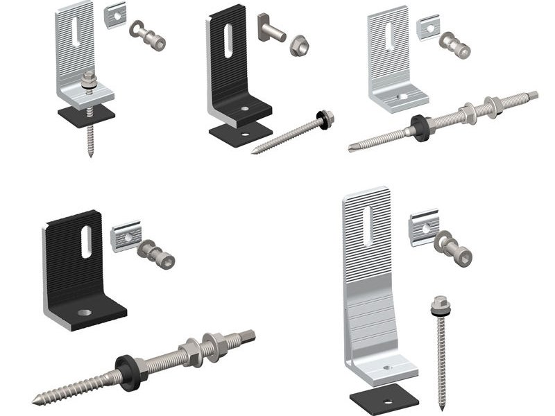
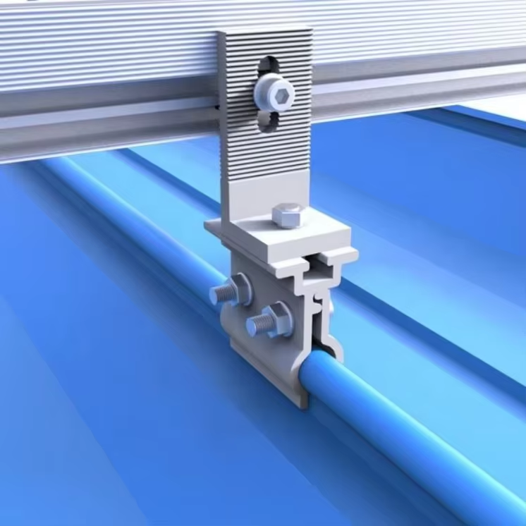
A solar L foot connects a photovoltaic (PV) mounting rail to a roof attachment or structural fixing. Depending on the mounting design, it may connect directly to a roof fixing or form part of a larger assembly that includes a tile hook, hanger-bolt bracket or other roof attachment.
Selecting an L foot is not simply a matter of choosing its dimensions or material thickness. The rail interface, T-bolt engagement, L-foot geometry, roof attachment, fastener, substrate and project loads all affect the performance of the complete connection.
The fundamental distinction is:
L-foot capacity ≠ roof-attachment capacity ≠ complete PV mounting-system capacity.
A sound selection process follows:
Rail compatibility → hardware engagement → roof-attachment compatibility → load-path assessment → installation requirements → evidence review → project design verification
1. What Does an L Foot Do in a Solar Mounting System?
An L foot is a mounting interface, typically with a base attached to a roof fixing or roof attachment and an upright section connected to a mounting rail.
Depending on the system, it may provide:
- A mechanical connection between the rail and roof attachment
- A defined rail mounting position
- Limited adjustment through a slot or other geometry
- An interface for specified T-bolts, nuts and washers
- A connection within a mounting system that may include bonding or grounding provisions
These functions are configuration-specific. An L foot that mechanically connects a rail to a roof attachment does not automatically establish the structural capacity, waterproofing performance, electrical bonding performance or project approval of the complete assembly.
Manufacturer documentation from Unirac, IronRidge and K2 illustrates how L-foot geometry, rail engagement, roof attachment and installation requirements are defined within particular mounting systems.
These documents should be used to understand the specified assembly—not as evidence that every L foot is interchangeable with every rail or roof attachment.
2. Understand the Complete Load Path
A typical load path is: PV module → module clamp → rail → L foot → roof attachment / fastener → roof structure
Where an intermediate component is used, the path may instead be: PV module → module clamp → rail → L foot → tile hook or hanger-bolt bracket → fastener → roof structure
The exact arrangement depends on the mounting architecture.
The complete connection may be governed by any of the following:
- Module clamp or module interface
- Rail and rail span
- T-bolt, nut, washer and rail channel
- L-foot geometry and material
- L-foot-to-roof-attachment connection
- Roof fastener
- Substrate or structural member
- Local roof structure
- Installation position and loading direction
A component’s nominal strength cannot establish the resistance of all these interfaces.
For example, an L foot may remain intact while the T-bolt connection slips, the roof fastener withdraws, the substrate fails or the rail connection governs.
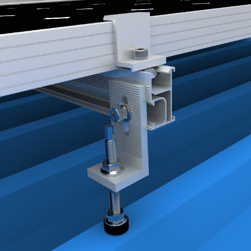
The engineering question is therefore not simply, “How strong is the L foot?” It is, “Which component or interface governs the complete load path under the defined project conditions?”
3. L-Foot-to-Rail Compatibility
The upper interface connects the L foot to the mounting rail. Physical fit is necessary, but it does not by itself establish structural qualification.
Before specifying the connection, identify:
- Rail manufacturer and model
- Rail cross-section and channel geometry
- Required T-bolt or rail fastener
- T-bolt head geometry and dimensions
- Nut and washer arrangement
- Permitted bolt orientation
- Required engagement
- Permitted attachment position
- Rail-end clearance, where specified
- Installation torque
- Bonding requirements, if applicable
3.1 A T-bolt that fits is not automatically qualified
A T-bolt may appear to fit a rail channel while differing from the specified hardware in head geometry, engagement, material, dimensions or installation orientation.
Those differences can affect the connection.
The applicable system documentation should define the required hardware and its installation. Do not assume that a generic T-bolt is interchangeable with the specified component merely because its nominal thread size matches.
3.2 Engagement and orientation matter
The T-bolt must engage the rail as intended by the mounting-system design. The permitted orientation, engagement position and any rail-end clearance should be checked against the relevant installation instructions.
An incorrectly positioned or incompletely engaged fastener may not provide the intended connection.
3.3 Torque is system-specific
Torque affects the installed connection, but a torque value is not a structural capacity rating.
Use the torque specified for the actual L foot, rail and fastener assembly. Do not transfer a value from another manufacturer’s system simply because the hardware appears similar.
The evidence registry identifies Unirac, IronRidge and K2 installation documents as useful sources for defined rail interfaces, T-bolt orientation and torque requirements. Their instructions remain specific to their documented systems.
4. L-Foot-to-Roof-Attachment Compatibility
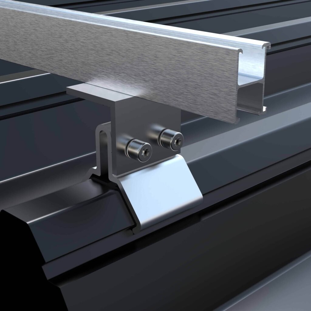
The lower interface must also be evaluated.
An L foot may connect to a roof attachment or structural fixing directly, or through a component such as a tile hook or hanger-bolt bracket.
Relevant inputs include:
- Roof type and covering
- Roof attachment type and model
- Fastener specification
- Structural substrate
- Structural-member dimensions
- Fastener position and edge distance
- Required embedment
- Installation access
- Roof penetration and sealing details, where applicable
The roof attachment and L foot are separate engineering elements.
A qualified L-foot-to-rail connection does not automatically qualify the lower attachment. Likewise, a strong roof fastener does not establish the capacity of the L foot, rail or complete system.
The actual connection geometry and supporting substrate must be considered together.
5. What Determines L-Foot Load Capacity?
There is no universal load rating that applies to all solar L feet.
Capacity depends on the defined configuration, including:
- L-foot dimensions and geometry
- Material, thickness and relevant material properties
- Leg height and flange dimensions
- Bend geometry
- Slot dimensions and bolt position
- Rail and T-bolt interface
- Roof attachment and fastener arrangement
- Substrate and support conditions
- Load direction
- Eccentricity
- Installation details
- Support spacing and the wider mounting system
The governing failure mode may occur in the L foot, rail, T-bolt connection, roof attachment, fastener, substrate or supporting structure.
A numerical capacity claim therefore requires a defined product and test or calculation basis. Without that information, publishing a generic kN value would be misleading.
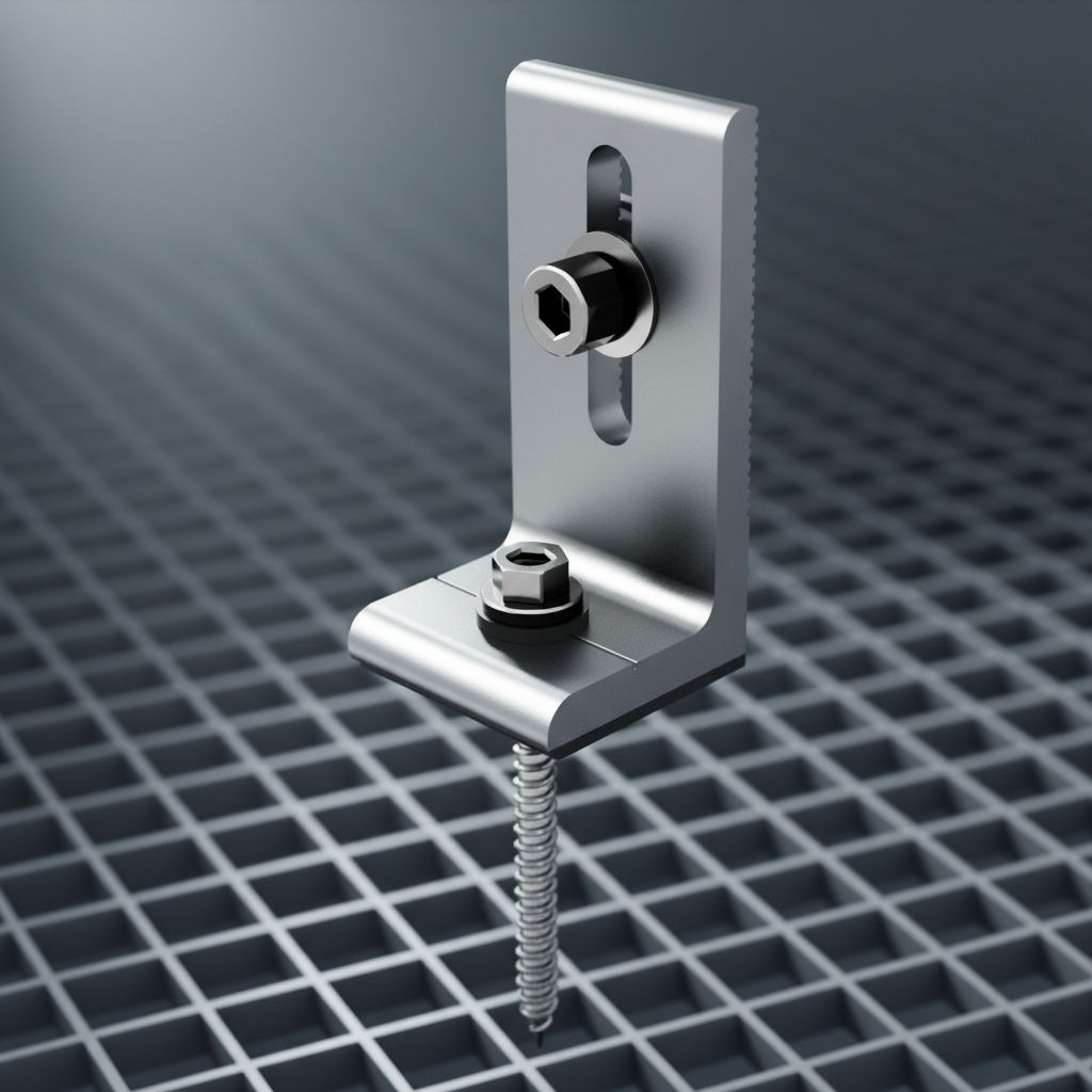
5.1 A thicker L foot is not automatically a proportionally stronger system
Thickness is one variable in the component’s structural behaviour. It does not independently establish the capacity of the complete connection.
Other factors may include:
- Material properties
- Leg and base geometry
- Bend radius
- Slot location
- Bolt position
- Lever arm
- Load direction
- Rail connection
- Roof attachment and substrate
A comparison between two thicknesses requires appropriate calculations or test evidence for the defined geometry and boundary conditions. It should not be presented as a universal percentage increase in capacity.
5.2 Component capacity is not system capacity
An isolated L-foot test may characterize the tested component under its stated conditions. It does not automatically establish the resistance of the rail connection, roof attachment or complete PV mounting system.
When evaluating evidence, identify the actual assembly and the failure mode that the test or calculation addresses.
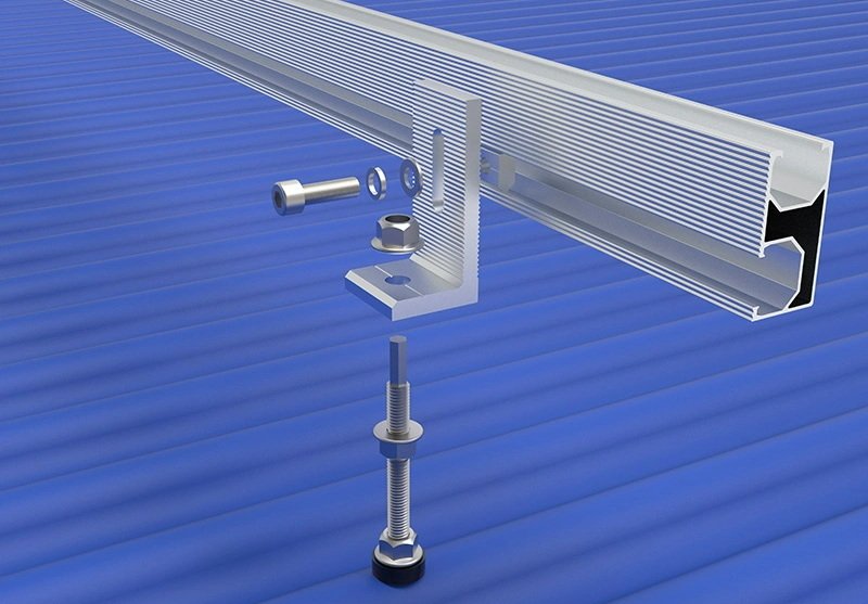
6. Slotted vs Fixed L Foot
A slotted L foot can provide adjustment for rail positioning or installation tolerances. A fixed-hole design may offer a different connection geometry and adjustment range.
The choice should be based on the installation requirements and the specified mounting configuration.
For a slotted L foot, check:
- Slot dimensions
- Permitted fastener position
- Required washer and hardware arrangement
- Available adjustment range
- Bolt position relative to the slot
- Installation limits
- Resulting eccentricity and load path
The position of the bolt within a slot can affect local stress and the geometry of the connection. Therefore, the allowable adjustment range and hardware position are part of the structural specification.
Adjustability is an installation feature, not proof of higher capacity.
IronRidge’s slotted L-foot and L-Mount documentation provide manufacturer-specific examples of adjustable geometry. Their details should not be generalized to products with different dimensions or installation conditions.
7. Bending and Eccentric Loading
L-foot geometry affects how loads are transferred between the rail and roof attachment.
Relevant variables include:
- Leg height
- Base and flange dimensions
- Material and thickness
- Bend radius
- Slot position
- Bolt location
- Rail position
- Load direction
- Eccentricity between the applied load and supporting connection
A longer lever arm can change bending demand even if the external roof load remains unchanged.
This means two L feet with the same material and nominal thickness may behave differently if their geometries or connection positions differ.
For engineering qualification, the relevant geometry and boundary conditions must be defined. A drawing establishes the shape and dimensions, but a drawing alone does not establish structural capacity.
Where the application requires it, representative testing or engineering calculations should assess the actual L-foot and connection configuration.
8. Roof Attachment and Waterproofing
The L foot is not, by itself, a waterproofing system.
Weather resistance depends on the complete roof-attachment detail, which may include:
Roof penetration → flashing or sealing components → alignment and compression → drainage → weather resistance
Relevant variables include:
- Roof type
- Attachment type
- Penetration position
- Flashing geometry
- EPDM or bonded washer, where specified
- Sealant or butyl, where specified
- Alignment
- Compression
- Drainage path
- Installation quality
- Environmental exposure
An EPDM washer or bonded washer does not, by itself, prove universal waterproofing performance.
Over-torque may damage sealing components in some systems. Conversely, using a sealing component without the correct installation detail may fail to achieve the intended result.
Manufacturer documentation such as Unirac FlashKit Pro, IronRidge ClickFit and IronRidge L-Mount provides examples of defined roof-attachment and sealing arrangements. Any performance claim should remain within the scope of the specific configuration and supporting evidence.
A water test on one assembly does not automatically qualify a different roof, penetration or installation detail.
9. Material Selection and Corrosion
L-foot material selection should consider the component and its environment, not just a material name.
Relevant factors include:
- Alloy or grade
- Material temper or relevant mechanical properties
- Component thickness
- Surface treatment or finish
- Fastener material
- Adjacent metals
- Moisture exposure
- Coastal or chloride exposure
- Trapped moisture and drainage
Material designation alone does not establish complete-system durability.
The compatibility of adjacent materials and the actual exposure environment should be evaluated. Anodizing or another surface treatment does not remove the need to assess the complete material combination.
Likewise, stainless-steel hardware is not automatically suitable for every environment or every contact with other metals.
Where corrosion performance is a project requirement, request relevant material specifications and environmental suitability evidence rather than relying on broad claims such as “corrosion-proof.”
10. Does an L Foot Provide Grounding or Bonding?
Mechanical attachment and electrical bonding are separate requirements.
Some PV mounting systems include qualified bonding hardware or components. Other L feet or hardware configurations should not be assumed to provide that function automatically.
Before making a bonding claim, verify:
- Whether the specific mounting system is qualified for bonding
- Which components are included in the evaluated configuration
- Which hardware and installation method are required
- Whether the claim applies to the intended rail and attachment arrangement
- What documentation defines the qualification scope
UL Solutions’ PV mounting-system certification information explains the role of defined product and system certification. The specific listing and its scope must be reviewed; a general reference to UL 2703 does not establish that every L foot or hardware combination provides qualified bonding.
Do not infer electrical bonding performance solely from metal-to-metal contact or mechanical continuity.
11. Installation Quality Is Part of the Engineering Specification
Even a suitable component can perform incorrectly if it is installed outside its specified configuration.
Before installation, confirm:
- Correct L-foot model and orientation
- Compatible rail and T-bolt
- Correct fastener and washer arrangement
- Required engagement
- Permitted slot position
- Roof-attachment alignment
- Pilot-hole preparation where specified
- Flashing or sealing procedure
- Required torque
- Any specified anti-seize or installation restrictions
- Bonding hardware and procedure, where applicable
Follow the installation instructions for the actual mounting system.
Do not substitute generic torque values or installation practices from another product without supporting evidence. Improper alignment, hardware engagement or sealing can change the intended load path or weathering performance.
12. What Engineering Evidence Should a Supplier Provide?
The evidence needed depends on the claim being made and the project’s qualification requirements.
Product and interface documentation
Request, where applicable:
- L-foot drawing and dimensions
- Material and finish specification
- Rail compatibility information
- T-bolt and hardware specification
- Permitted bolt positions
- Roof-attachment interface
- Installation instructions
- Torque requirements
- Bonding documentation, if claimed
Waterproofing and material evidence
Where relevant, request:
- Roof-attachment and flashing detail
- Sealing-component specification
- Installation procedure
- Weathering or water-test scope
- Material and surface-treatment specification
- Environmental suitability information
Structural evidence
Where a capacity or structural qualification is required, useful evidence may include:
- Defined structural test reports
- Engineering calculations
- Connection testing
- L-foot bending assessment
- T-bolt engagement or rotation testing
- Roof-attachment-to-L-foot testing
- Fastener and substrate evidence
- Project-specific wind and other applicable load calculations
A meaningful test report should identify the L foot, material, thickness, geometry, rail, T-bolt, nut and washer, roof attachment, fastener, substrate, support conditions, loading direction, test method, boundary conditions, failure mode and result.
A result without adequate configuration information may not be applicable to the proposed project.
What the evidence does not establish automatically
- A CAD drawing does not establish structural capacity.
- Installation torque is not structural capacity.
- An isolated L-foot test does not automatically qualify the complete mounting system.
- A manufacturer’s system guide does not establish universal interchangeability.
- A certification statement does not cover configurations outside its documented scope.
The evidence must match the actual engineering question.
13. How to Select an L Foot for a Project
A practical selection sequence is:
Step 1 — Identify the rail
Confirm the rail manufacturer, model, cross-section, channel geometry and specified fastener.
Step 2 — Define the roof attachment
Identify whether the L foot connects directly to a roof fixing or to another attachment component, such as a tile hook or hanger-bolt bracket.
Step 3 — Check the lower connection
Confirm the fastener, substrate, structural-member dimensions, attachment position and applicable installation requirements.
Step 4 — Select the L-foot geometry
Define the required leg height, base dimensions, slot or hole geometry, material, thickness, finish and adjustment range.
Step 5 — Verify the complete connection
Review the rail interface, L foot, roof attachment, fastener and substrate as one load path. Identify the potential governing failure modes.
Step 6 — Check waterproofing and bonding separately
Confirm the roof weathering detail and any qualified bonding arrangement. Do not assume that structural suitability establishes either function.
Step 7 — Review the evidence
Match the available drawings, installation documentation, test reports and calculations to the actual configuration.
Step 8 — Complete project design verification
Use the applicable project design requirements and loads. Component-level evidence should not be substituted for the structural verification required for the complete mounting arrangement.
14. What Information Should Be Included in an L-Foot RFQ?
A useful request for quotation should contain enough technical information to evaluate compatibility and identify missing engineering evidence.
Rail
- Manufacturer and model
- Cross-section and channel dimensions
- Required T-bolt and hardware
- Rail span and intended orientation
- Bonding requirements, if applicable
Roof attachment
- Roof type and covering
- Attachment type and model
- Fastener specification
- Substrate or structural-member dimensions
- Roof penetration and flashing requirements
- Existing roof-attachment drawings or photographs
L foot
- Fixed-hole or slotted design
- Required leg height
- Base and slot dimensions
- Material and thickness
- Finish
- Hardware arrangement
- Adjustment range
- Required rail interface
Engineering
- Project location
- Applicable design code
- Wind and snow requirements, where applicable
- Roof zone
- Module arrangement
- Rail span and L-foot spacing
- Roof structural information
- Required calculations, tests or certification documentation
Procurement
- Quantity
- Target market
- Delivery requirements
- Sample requirement
- OEM/ODM requirements
- CAD and documentation requirements
- Testing or qualification requirements
If key inputs are not available, identify them as open items rather than assuming a standard configuration.
15. Standards and Certification: Check the Scope
Standards and certification frameworks can support product evaluation, but they should not be used to imply that an unverified configuration is qualified.
For PV mounting systems, UL Solutions describes UL 2703 as covering mounting systems, mounting devices, clamping or retention devices and ground lugs within a defined certification scope. The specific listing and its limitations must be checked for the intended product and application.
For PV array design, IEC 62548-1 provides a relevant international design framework within its defined scope. It does not establish a universal capacity for every L foot.
Where Standards Australian or Standards New Zealand projects are involved, the applicable local design and installation requirements must be identified for the project. A general reference to a standard does not prove that a particular L foot has been tested, certified or approved under that standard.
The correct relationship is:
Applicable requirements → defined mounting configuration → relevant evidence → project-specific verification
not:
Standard mentioned → product automatically approved
16. Common L-Foot Selection Mistakes
Mistake 1 — Choosing by dimensions alone
Similar dimensions do not prove compatibility with the rail, T-bolt, roof attachment or intended load path.
Mistake 2 — Assuming any T-bolt will work
The specified hardware, engagement, orientation and installation requirements must be checked.
Mistake 3 — Treating L-foot capacity as system capacity
The rail, attachment, fastener, substrate and other interfaces may govern.
Mistake 4 — Assuming thicker means proportionally stronger
Thickness is only one variable; geometry and connection conditions also matter.
Mistake 5 — Ignoring slot position
The bolt position and permitted adjustment range affect connection geometry and may affect eccentricity.
Mistake 6 — Using a universal torque value
Torque must come from the applicable system documentation.
Mistake 7 — Treating an EPDM washer as complete waterproofing
Weather resistance depends on the complete roof-attachment detail and installation.
Mistake 8 — Assuming the L foot automatically provides grounding
Bonding must be established for the relevant qualified configuration.
Mistake 9 — Using an isolated test as proof of the whole system
Test scope, boundary conditions and failure mode must match the claim being made.
17. Product and Engineering Boundary
An L foot should be treated as one interface in a complete PV mounting system.
Its structural role connects the rail to a roof attachment, but the engineering assessment must also consider the rail, T-bolt, fastener, substrate and supporting structure.
Waterproofing and electrical bonding are separate functions requiring their own applicable evidence.
The essential distinctions are:
- L-foot capacity is not roof-attachment capacity.
- Roof-attachment capacity is not complete system capacity.
- Physical fit is not structural qualification.
- A slot is an adjustment feature, not proof of higher capacity.
- A material designation is not complete-system durability evidence.
- Mechanical attachment does not automatically establish bonding.
- A sealing component does not automatically establish waterproofing performance.
- A test result applies to its defined configuration and scope.
A defensible selection follows:
Compatibility → Qualification → Project Design
Conclusion
A solar L foot should be selected as part of a defined rail-to-roof-attachment configuration, not as an isolated metal bracket.
The essential checks are:
- Does the L foot match the rail and specified hardware?
- Is the T-bolt correctly engaged and installed?
- Is the lower roof attachment appropriate for the substrate?
- Have geometry, eccentricity and the complete load path been considered?
- Are waterproofing and bonding requirements addressed separately?
- Does the available evidence support the actual configuration and intended claim?
- Has the complete arrangement been verified for the project requirements?
Where these questions remain unanswered, the next step is to obtain the missing drawings, substrate information, installation requirements or engineering evidence—not to assume a universal capacity or compatibility.
Have a specific rail and roof attachment?
Send us the rail cross-section, T-bolt requirements, L-foot dimensions, roof-attachment details and project requirements. We can review interface compatibility and identify the information needed for qualification before quotation or sample development. dapibus.