
Solar Panel Gap and Mid Clamp Selection: How to Verify the Correct Fit
The gap between adjacent solar panels should be determined by the requirements of the selected mounting system and the module manufacturer’s installation instructions. It should not be chosen from a generic spacing rule alone.
A mid clamp must fit between the two module frames, engage both frames as intended, and connect correctly to the mounting rail. The specified module gap is therefore part of the clamp interface—not simply an aesthetic choice or a dimension to fill during installation.
A suitable selection process checks four things together:
The module manufacturer’s mounting requirements.
The mid clamp’s geometry and engagement with both frames.
The mounting rail and fastener interface.
The gap and installation method specified for the complete mounting system.
There is no single module-to-module gap that applies to every solar mounting system.
1. Why the module gap matters
A framed-module mid clamp sits between two adjacent modules and applies clamping force to both frames. Its position and geometry must allow both sides of the clamp to engage the intended frame surfaces.
An unsuitable gap can create several problems:
Insufficient clearance: The modules may not leave enough space for the specified clamp body or installation method.
Incomplete engagement: One or both clamp sides may not contact the intended frame surfaces correctly.
Incorrect positioning: The clamp may be forced into a position that does not match the manufacturer’s installation procedure.
Installation misalignment: The modules, clamp and rail fastener may not align as intended.
Unverified mounting configuration: Even if the clamp appears to fit, the resulting arrangement may differ from the configuration used in the module’s mechanical-load qualification or the mounting system’s evaluation.
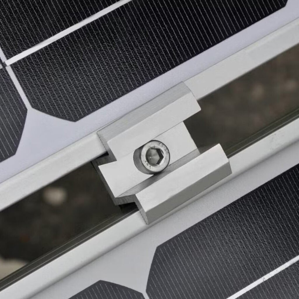
The critical distinction is that physical fit alone does not establish correct installation or structural qualification.
2. What determines the correct module gap?
The gap is governed by the actual module-and-mounting-system interface. The following factors should be checked together.
2.1 The mounting-system manufacturer’s instructions
Start with the installation manual for the exact rail and mid-clamp system.
The manual may specify:
The required module-to-module spacing.
How the second module should be positioned against the clamp.
The intended clamp engagement with both module frames.
The orientation and engagement of the T-bolt or other rail fastener.
Any restrictions on installation sequence or component reuse.
These requirements are system-specific. Do not transfer a spacing value from one manufacturer’s rail-and-clamp system to another without confirmation.
For example, IronRidge’s roof-mount installation documentation describes a particular sequence for placing the second module, engaging the mid clamp and tightening the connection. Its stated dimensions and procedures apply to that documented system, not to every mid clamp.
Reference: IronRidge Roof Mount Installation Manual
2.2 The module frame geometry
The module’s nominal frame height is only one part of the interface.
Also verify, where relevant:
Frame thickness and flange geometry.
The surfaces intended for clamp contact.
The manufacturer’s approved clamping zone.
Any restrictions on the mounting method or clamp position.
Whether the module design permits the proposed clamp arrangement.
Two modules may have the same nominal frame height but differ in flange shape or other details that affect clamp engagement.
The selected gap must work with the actual frame geometry and the clamp design. A dimension that appears suitable in a general drawing is not sufficient evidence of compatibility.
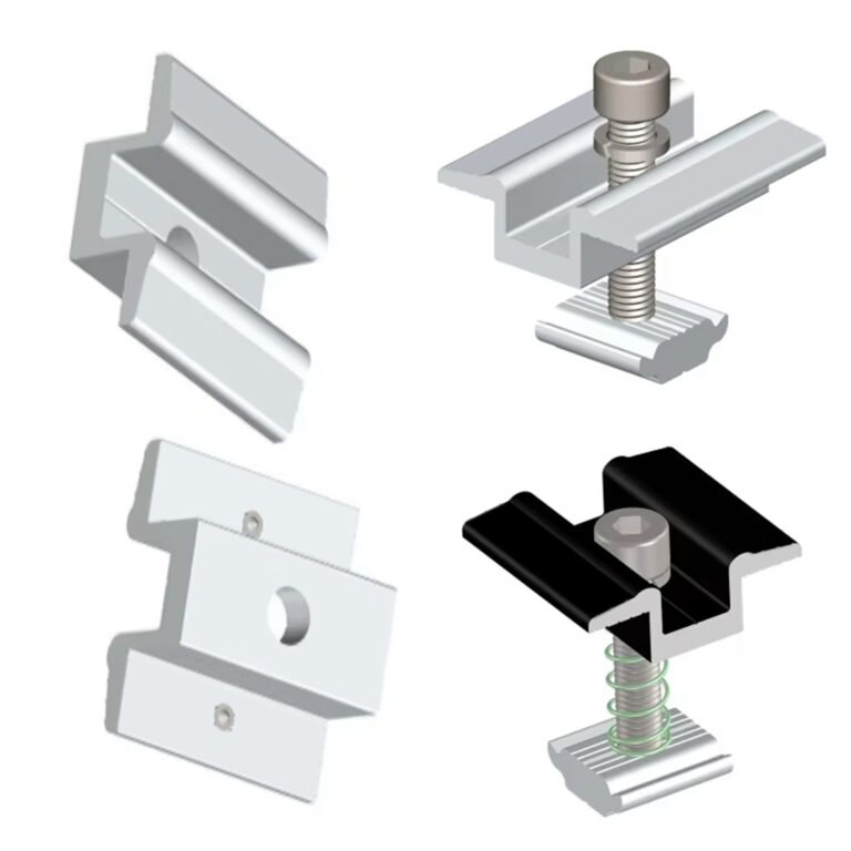
2.3 The mid-clamp geometry
The clamp itself determines how it occupies the space between adjacent frames.
Relevant dimensions may include:
Clamp body width.
The geometry of each contact face.
The intended engagement or overlap with each frame.
The relationship between the clamp body and the rail fastener.
Any product-specific positioning features.
A clamp that is too wide for the specified arrangement may prevent the modules from reaching the intended position. A clamp with unsuitable contact geometry may fail to engage both frames as designed.
Do not assume that changing the module gap will correct an incompatible clamp. The correct solution may instead require a different clamp design or a mounting-system-approved configuration.
2.4 The rail and fastener interface
The clamp must also work with the selected rail and its fastening hardware.
Check the rail channel, T-bolt or other fastener, engagement position and installation sequence. A clamp that fits between two frames may still be unsuitable if its base or fastener does not match the rail.
The module gap, clamp geometry and rail interface should therefore be checked as one assembly.
3. Is there a standard gap between solar panels?
There is no universal gap suitable for all framed-module mounting systems.
Published manufacturer instructions demonstrate why a generic number should not be treated as a universal requirement.
For example, the IronRidge Roof Mount manual describes a specific installation sequence involving a stated gap and subsequent positioning of the second module against the clamp. Unirac’s SolarMount installation documentation also distinguishes layout requirements by system configuration.
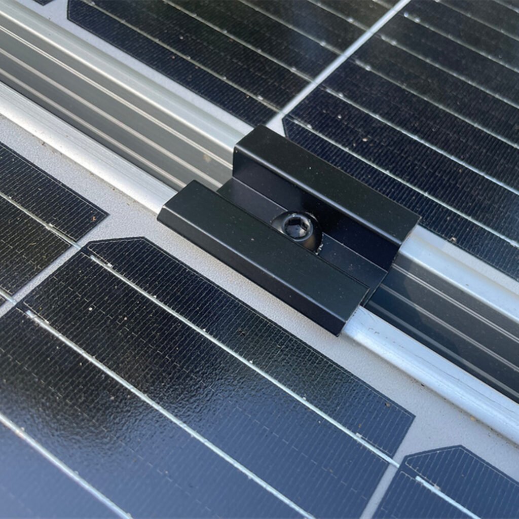
These examples are evidence of product-specific installation requirements—not a basis for applying either manufacturer’s dimensions to unrelated hardware.
References:
When a drawing, product page or installer asks for a particular gap, confirm what that dimension represents. It may refer to the intended space between module frames, a layout allowance used to calculate rail length, or a dimension within a particular installation sequence. These measurements should not be treated as interchangeable without checking the relevant drawing and instructions.
If the mounting-system manual and module manufacturer’s requirements appear inconsistent, obtain clarification from the responsible manufacturers or project engineer rather than selecting an arbitrary compromise.
4. How to verify a mid clamp against the required gap
Use the following sequence before approving a clamp for procurement or installation.
Step 1 — Identify the exact module
Record the module manufacturer and model, not only its rated wattage or overall dimensions.
Obtain the relevant installation manual and confirm the approved mounting method and clamping zone.
Step 2 — Identify the rail and mid clamp
Record the rail manufacturer and model, mid-clamp part number, and applicable installation documentation.
If the clamp is supplied as part of a complete mounting system, use the instructions for that specific system.
Step 3 — Confirm the required gap
Find the specified module spacing and installation sequence in the applicable documentation.
If no clear value is available, ask the mounting-system supplier to confirm the required spacing for the proposed module and clamp combination. Do not substitute a generic industry value.
Step 4 — Check engagement with both frames
Confirm that the clamp can engage both intended module frames in the specified position.
Review the contact geometry, engagement depth or overlap where specified, and any restrictions associated with the frame design.
A drawing showing that the clamp fits between the modules is not enough if it does not demonstrate the intended contact and installation arrangement.
Step 5 — Verify the rail connection
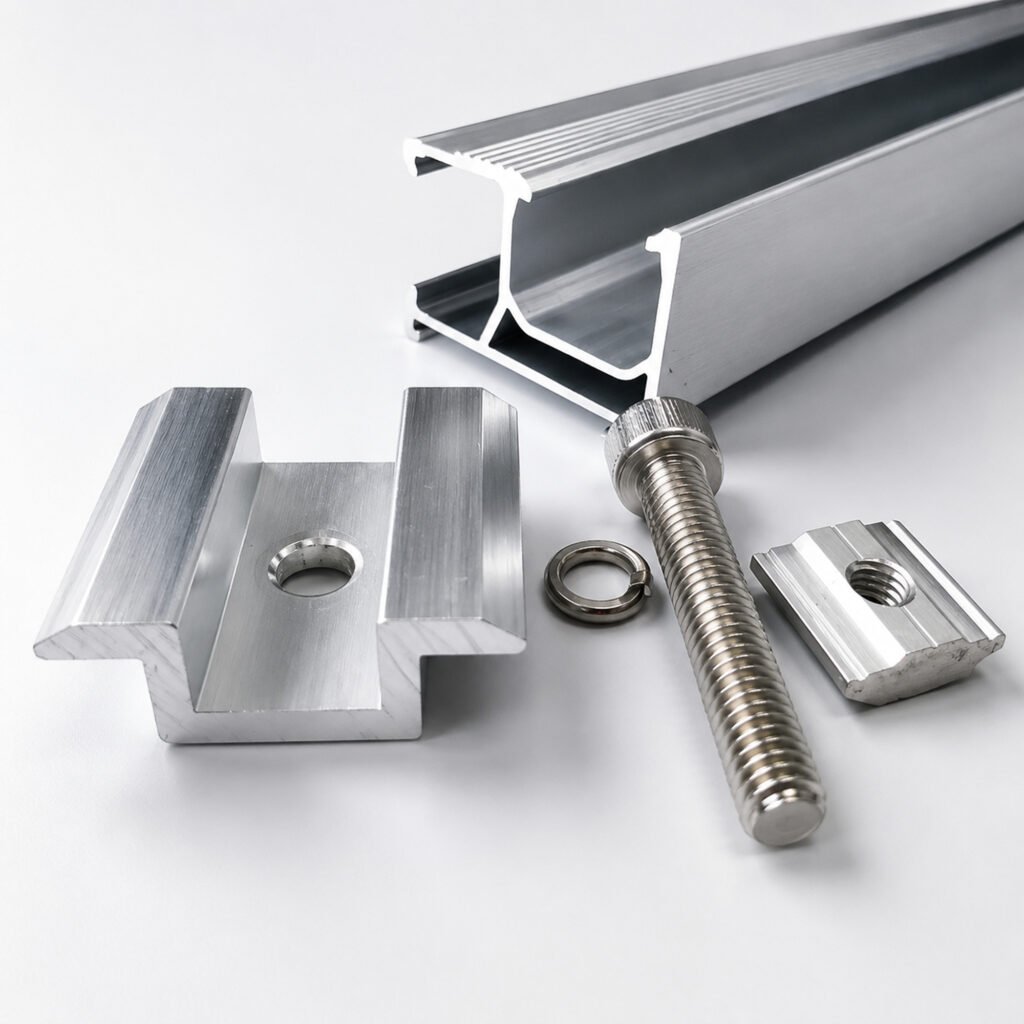
Check the fastener type, rail channel compatibility, engagement and orientation required by the installation manual.
Do not assume that a clamp designed for one rail can be used with another rail simply because the fastener can be inserted.
Step 6 — Confirm the qualified configuration
Check whether the proposed combination is covered by the relevant manufacturer’s instructions, engineering documentation or applicable system evaluation.
Where structural performance is important, verify that the module, clamp, rail and attachment arrangement is consistent with the documented configuration. A physical-fit check alone does not establish structural suitability.
5. What if the specified gap does not work with the selected clamp?
Do not force the modules into position or alter the gap without checking the applicable requirements.
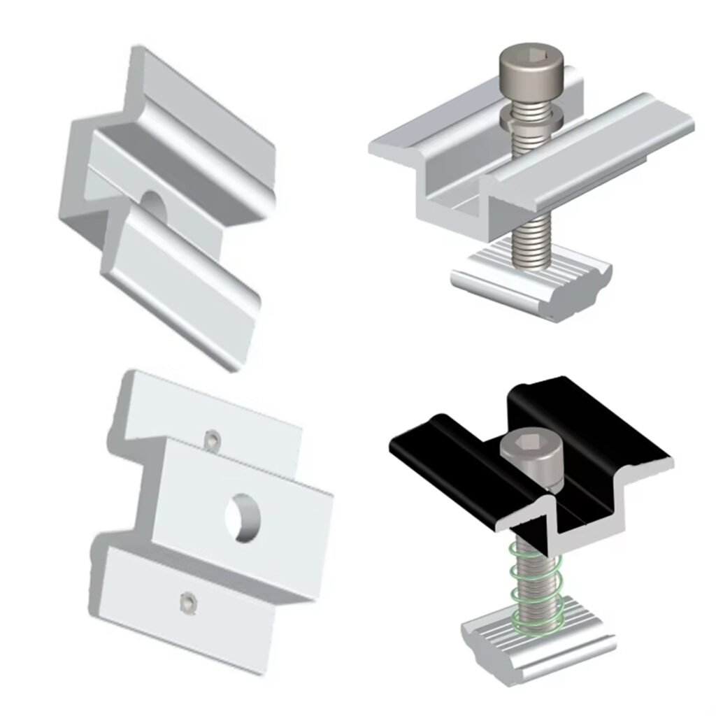
Investigate the source of the mismatch:
| Observed issue | What to check |
|---|---|
| The modules cannot reach the intended position | Required gap, clamp body width and installation sequence |
| The clamp does not contact both frames as intended | Frame geometry, contact surfaces and clamp design |
| The clamp fits but does not align with the rail fastener | Rail channel, fastener dimensions and clamp-to-rail compatibility |
| The installation differs from the approved module arrangement | Module manual, approved clamping zone and mounting-system instructions |
| The drawings give conflicting dimensions | Drawing revisions, measurement definitions and manufacturer clarification |
Depending on the cause, the appropriate action may be to select another compatible clamp, correct the rail or module specification, or obtain an approved installation detail.
Do not solve a dimensional problem by increasing tightening force. Torque must follow the applicable product instructions, and tightening harder does not establish correct engagement or compatibility.
6. Information to request from a mid-clamp supplier
For a new project or OEM/ODM inquiry, provide enough information to check the actual interface.
Module
Manufacturer and exact model.
Frame height, thickness and relevant flange geometry.
Installation manual or approved clamping-zone drawing.
Required module-to-module gap, if already specified.
Mounting system
Rail manufacturer and model.
Rail cross-section or interface drawing.
Mid-clamp part number or dimensional drawing.
Fastener type and installation requirements.
Qualification
Applicable system documentation or evaluation.
Confirmation of the intended module-and-rail combination.
Any project-specific mechanical or certification requirements.
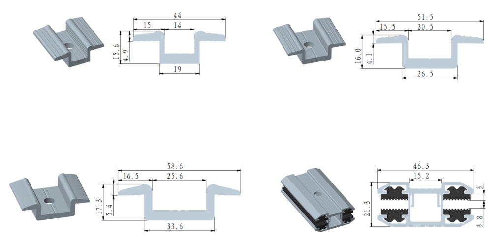
If a custom mid clamp is being developed, the supplier should review the module frame, required gap, contact geometry, rail interface and installation method together. A CAD drawing can establish dimensional compatibility, but it does not by itself demonstrate structural performance.
Frequently asked questions
What gap should I leave between solar panels?
Follow the installation instructions for the exact mounting system and confirm compatibility with the module manufacturer’s mounting requirements. Do not apply a universal gap to all systems.
Can I use a wider gap if the mid clamp does not fit?
Not automatically. First determine whether the issue comes from the clamp geometry, module frame, rail interface or specified installation method. Any change must remain consistent with the applicable requirements.
Can the same mid clamp work with different module gaps?
That depends on the clamp design and the specific mounting system. A clamp should not be assumed to accommodate different gaps unless the manufacturer documents the permitted arrangements.
Does a mid clamp that fits between two panels mean it is compatible?
No. Physical fit does not establish correct frame engagement, rail compatibility, manufacturer approval or structural qualification.
Can I select a mid clamp using only the module frame height?
No. Frame height is one input. Frame geometry, the required gap, clamp engagement, rail interface and applicable installation requirements must also be checked.
What should I do if the module and mounting-system manuals disagree?
Ask the relevant manufacturers or responsible project engineer to resolve the discrepancy before installation. Do not assume that one instruction can be ignored or that a compromise dimension is acceptable.
Conclusion
Correct mid-clamp selection starts with the actual module and mounting system—not with a generic gap dimension.
Confirm the required module spacing, check that the clamp engages both frames as intended, verify the rail and fastener interface, and establish that the proposed configuration is supported by the applicable documentation.
A suitable gap is one that works within the specified module-and-mounting-system arrangement. It is not a universal number that can be selected independently of the hardware.