
Standing Seam Clamp Load Capacity: What Actually Governs?
A standing seam clamp does not have one universal load capacity. Its resistance depends on the clamp, the roof seam, the load direction and the way the roof transfers loads into the supporting structure.
This is why a load value shown on a product page should not be used without checking the test configuration and the intended application.
A clamp may remain intact while the seam deforms or slips. Under some loading conditions, the governing limit may be the roof panel, its clips or the supporting structure rather than the clamp itself.
To evaluate a standing seam clamp properly, start with the complete load path and the relevant failure mode—not just the clamp’s material or dimensions.
1. What Does a Standing Seam Clamp Load Rating Actually Describe?
A load rating is meaningful only when its basis is clear.
Before comparing two values, establish whether each refers to:
A clamp tested on a specific seam profile
A particular roof material and thickness
A defined load direction
A specific clamp model and installation procedure
A test-to-failure result, an allowable value or a design resistance
An individual connection or a larger roof assembly
These are not interchangeable descriptions.
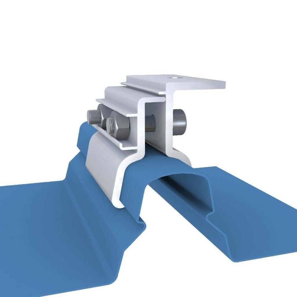
For example, a reported ultimate load from a clamp-to-seam tensile test is not automatically the allowable load for project design. Converting a test result into a design value requires an appropriate engineering method, including the relevant safety or reduction factors and confirmation that the test configuration represents the proposed installation.
If the source does not explain what the number represents, the number alone is insufficient for engineering approval.
2. The Roof Seam Is Part of the Connection
A standing seam clamp transfers load through contact with the seam. Depending on the clamp and seam geometry, resistance may involve mechanical engagement, friction, local deformation or a combination of these mechanisms.
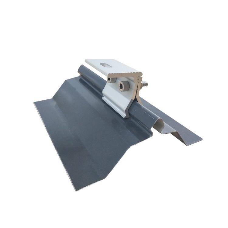
The clamp cannot be assessed independently of the seam it grips.
Important variables include:
Seam height, width and cross-sectional shape
Folded, rolled or other seam geometry
Roof-panel material and thickness
Clamp body and contact geometry
Set-screw arrangement and specified installation torque
Load direction
Local seam deformation and surface condition
A clamp that fits physically may still be unsuitable for the intended load case. The contact geometry may differ, the seam may deform locally, or the connection may not have been tested in the required direction.
The correct starting point is the actual roof profile and the manufacturer’s compatibility information—not a general roof label such as “standing seam.”
3. Load Direction Can Change the Result
Standing seam clamps may be subjected to loads in more than one direction. Two important test orientations are:
Normal-to-seam loading: the load acts perpendicular to the roof surface, such as an uplift force pulling the clamp away from the roof.
Parallel-to-seam loading: the load acts along the seam, sometimes described as a drag load.
These orientations engage the connection differently. A result obtained in one direction should not automatically be applied to the other.
S-5!, for example, publicly describes tensile testing in both normal-to-seam and parallel-to-seam directions. Its published testing information also identifies the roof profile, material, thickness and clamp model as relevant variables. This is a manufacturer’s stated testing approach, not a universal protocol or a substitute for checking the specific test report.
For project qualification, confirm the direction of the design action and check whether the available evidence covers that direction. Where multiple load components act together, the applicable engineering assessment may need to consider their combined effects.
4. Which Part of the Assembly Governs?
The clamp is only one component in the load path.
A typical standing seam roof assembly may transfer loads through:
PV module → module clamp → rail → standing seam clamp → roof seam and panel → panel clips → purlins or supporting structure
The exact arrangement varies by roof system. Some systems have different clip types, panel restraints, support spacing or movement details.
Potential governing mechanisms include:
Slip or separation at the clamp-to-seam interface
Local yielding, denting or opening of the seam
Deformation or failure of the roof panel
Failure or disengagement of panel clips
Fastener failure at the panel support
Purlin or other supporting-structure deformation
Failure at another component in the mounting load path
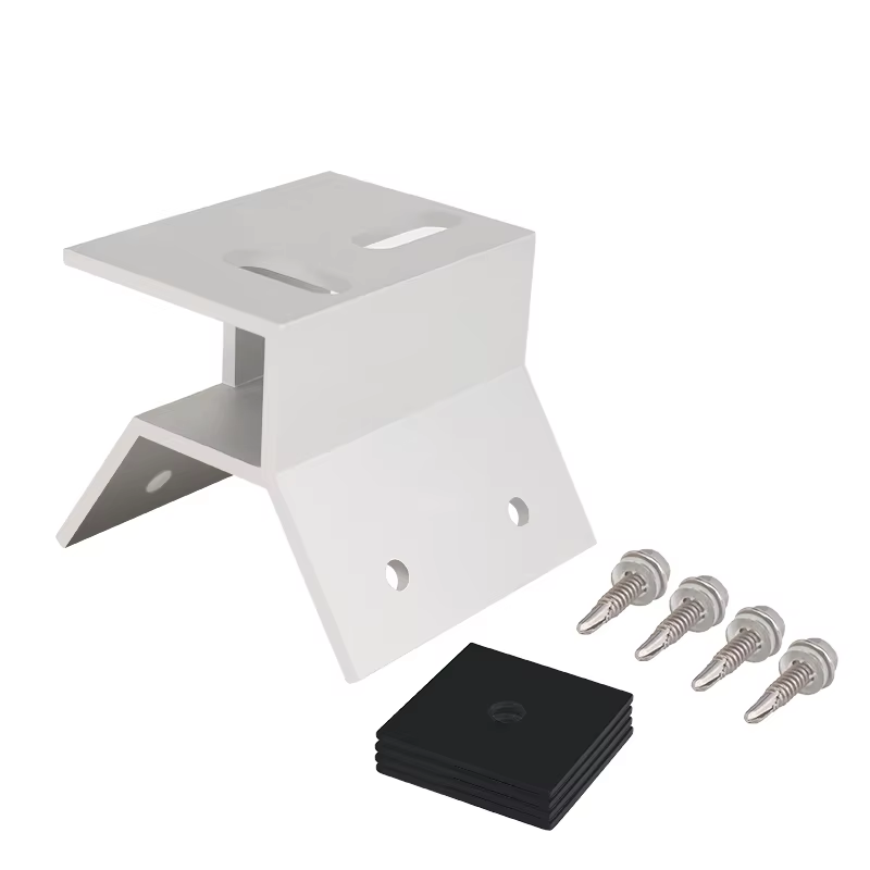
A strong clamp does not guarantee a strong roof assembly. Equally, a roof panel with substantial overall strength does not prove that the local clamp-to-seam connection is adequate.
Research into standing seam roof systems under wind uplift has documented multiple failure mechanisms and shown that load paths and load sharing can change as roof panels deform. The findings are specific to the tested assemblies, but they reinforce an important engineering principle: the governing failure point must be established for the actual system.
5. Why Seam Profile, Material and Thickness Matter
Standing seam roofs are not one standardized interface. Profiles that look similar may differ in seam geometry, material, thickness, folding details and how the panels are supported.
Those differences can affect how the clamp engages the seam and how the seam responds under load.
Seam profile and geometry
The clamp must engage the intended seam geometry. A different seam shape can change contact, mechanical engagement and local deformation. Do not assume that compatibility with one profile proves compatibility with another.
Material and thickness
Steel and aluminum panels may behave differently, and thickness is only one part of the material description. The relevant material properties and the specific seam configuration also matter.
A result for one material or thickness should not be transferred to another without an appropriate technical basis.
Panel and clip arrangement
The seam is connected to the building through the roof system’s support details. Panel width, clip arrangement, support spacing and restraint conditions may affect the overall response, particularly under uplift.
The clamp’s own test result cannot independently qualify these other parts of the roof assembly.
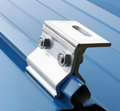
6. How to Read a Standing Seam Clamp Test Report
A useful report should allow an engineer to determine what was tested, what failed and how the result may be used.
Confirm the specimen
Look for:
Roof-panel manufacturer or identifiable profile
Seam geometry and dimensions
Panel material and thickness
Clamp model and configuration
Fastener or set-screw arrangement
Installation instructions and applied torque
Relevant support and boundary conditions
If critical specimen details are missing, it may be impossible to establish whether the result applies to the proposed roof.
Confirm the load direction
Identify whether the test applied load normal to the seam, parallel to the seam or in another configuration. Do not treat these results as interchangeable.
Read the failure description
A report should identify the observed failure mode, not just the maximum load.
Check whether the clamp slipped, the seam yielded or opened, a clamp component broke, or another part of the specimen failed. Photographs and test observations can help establish whether the result reflects clamp resistance or a different limit in the assembly.
Check the test method and laboratory information
Review the test procedure, specimen preparation, number of tests, reported results and laboratory details. If the report refers to an accredited laboratory, confirm what the accreditation covers where that information is material to the qualification.
ASTM E1592 addresses structural performance testing of sheet-metal roof and siding systems under uniform static air-pressure differences. Its scope should not be confused with a universal clamp-to-seam product rating method. The applicable test method depends on the engineering question being asked.
Establish how the result is used
A test-to-failure value, an allowable holding value and a project design resistance serve different purposes.
The design process must use the applicable methodology and account for the representative configuration, relevant factors and project load requirements. A peak load should not be copied directly into a design schedule without establishing its engineering meaning.
7. What About Roof Movement and Manufacturer Requirements?
Standing seam roof systems may be designed to accommodate thermal movement. A mounting attachment must not unintentionally restrain movement in a way that conflicts with the roof system’s design.
Check whether the proposed clamp is intended to be fixed or sliding, how it interacts with the rail, and whether the arrangement is compatible with the roof manufacturer’s requirements.
Also check warranty conditions and any installation limitations that apply to the roof system. A clamp’s load test does not, by itself, establish compatibility with every roof manufacturer’s requirements.
8. A Practical Qualification Checklist
Before accepting a standing seam clamp for a project, confirm the following.
Roof information
Roof manufacturer and exact profile
Seam shape and dimensions
Panel material and thickness
Panel support and clip arrangement, where available
Relevant roof movement requirements
Clamp information
Exact clamp model
Documented compatibility with the seam
Installation instructions and specified torque
Intended fixed or sliding function, where relevant
Applicable certification or listing scope, if required by the project
Engineering evidence
Test configuration and load direction
Tested roof profile, material and thickness
Number of specimens and reported results
Observed failure modes
Test method and laboratory details
Explanation of how the result relates to allowable or design resistance
Any restrictions or exclusions
Project design
Project location and applicable design requirements
Relevant wind loads and roof zones
Load distribution and proposed attachment layout
Roof-system capacity and support conditions
Confirmation that the tested or calculated configuration is representative
If the profile, loading direction or intended use is not covered by the available evidence, obtain additional documentation or a project-specific engineering assessment before treating the clamp as qualified.
FAQ
Does a standing seam clamp have one universal load capacity?
No. Capacity depends on the clamp model, seam geometry, roof material and thickness, load direction, installation and the tested configuration. A single number without this context can be misleading.
Is a clamp’s ultimate test load the same as its design capacity?
No. Ultimate test load describes the result under a particular test. Project design resistance or allowable load must be established using the applicable engineering methodology and representative evidence.
Can a clamp tested for uplift also be used for parallel-to-seam loads?
Not automatically. Normal-to-seam and parallel-to-seam loading engage the connection differently. Check the test evidence and engineering basis for the required direction.
If the clamp does not break, has the connection passed?
Not necessarily. The seam or another part of the roof assembly may govern. The observed failure mode matters as much as the peak load.
Does a clamp test prove the capacity of the complete roof?
No. A clamp-to-seam test addresses a defined part of the load path. The roof panel, panel clips, fasteners and supporting structure may require separate or system-level verification.
Conclusion
Standing seam clamp capacity is a property of a defined connection and test configuration—not an isolated number that applies to every roof.
The seam profile, material and thickness, load direction, clamp installation, failure mode and supporting roof system all affect the engineering assessment. Test results should be used only within their documented scope, with a clear distinction between ultimate test load and project design resistance.
For a reliable selection, identify the exact roof profile, define the required load directions, review the test evidence and establish whether the complete load path is adequately addressed.
Need to check a standing seam clamp for your project?
Send us the roof profile, panel material and thickness, required load directions and available test documentation. We can help identify the information needed to assess compatibility and qualification.