
Tile Hook to Rafter Load Path: How Solar Loads Reach the Roof Structure
A solar tile hook is only one part of the roof attachment. Its ability to transfer load depends on the hook geometry, fasteners, supporting rafter, rail connection and the way the complete mounting system is installed.
For a conventional rail-based system, the structural load path is typically:
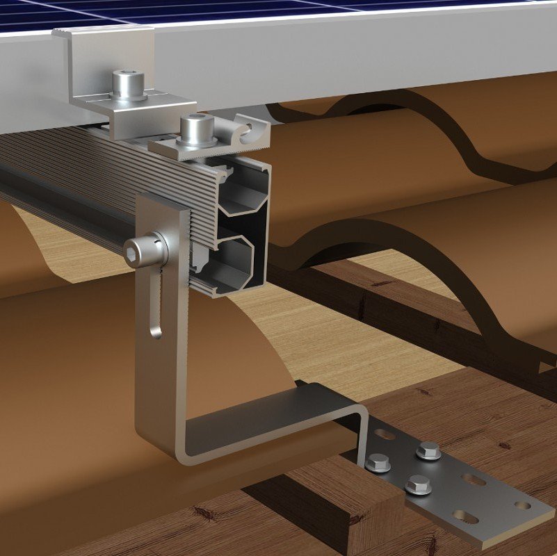
PV module → module clamps → rail → tile hook → roof fasteners → rafter → roof structure
Every connection in this chain must be suitable for the loads it receives. A strong hook cannot compensate for inadequate fastener engagement, a narrow or damaged rafter, or a poorly configured rail connection.
The roof tile has a different role. It is part of the roof covering and weather-protection arrangement; it should not automatically be treated as the structural support for the PV mounting system.
1. Follow the complete load path
The first step in evaluating a tile-hook attachment is to identify how forces travel from the PV array into the building structure.
Module and rail interface
Wind uplift, downward loading and other project actions are transferred from the modules through their approved clamping locations into the rails.
The rail then distributes these actions to the roof hooks according to the rail span, hook spacing, array layout and connection arrangement.
A module clamp that fits the frame does not, by itself, establish the capacity of the rail or roof attachment. Each interface must be compatible with the mounting system and module requirements.
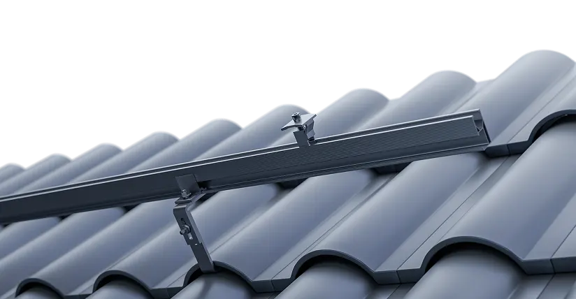
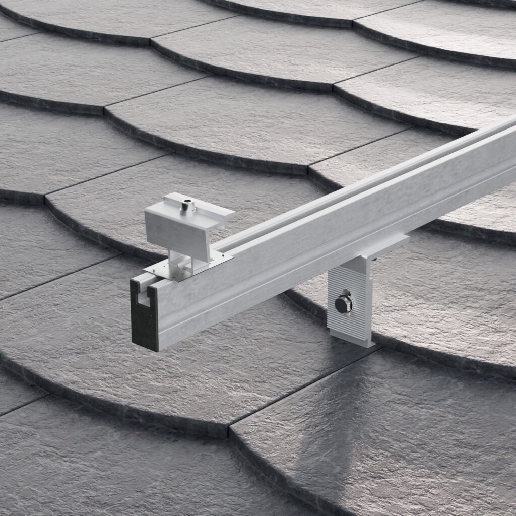
Tile hook and fastener connection
The hook transfers load to its fasteners. Depending on the geometry and loading, the hook may experience bending while the fasteners and supporting timber resist forces in different directions.
The connection must be assessed as an assembly rather than by looking at the hook’s material or dimensions alone.
Relevant questions include:
Is the hook designed for the intended rail and tile-roof configuration?
How many fasteners are required, and what type and dimensions are specified?
Are the fasteners installed into the intended structural member?
Is the timber suitable and in sound condition?
Are the required embedment and edge distances achieved?
Does the installed geometry match the configuration covered by the manufacturer’s instructions or engineering evidence?
Rafter and roof structure
The rafter receives the forces transferred through the fasteners and passes them into the wider roof structure.
The rafter connection is therefore not the end of the assessment. The supporting member, its dimensions and condition, its connections to the surrounding structure, and the building’s load-resisting system may all affect whether the complete arrangement is adequate.
A roof hook that is correctly installed does not automatically demonstrate that the existing roof structure can carry the additional PV loads.
2. Why the roof tile should not be treated as the main structural support
Roof tiles vary in material, profile, thickness, overlap and geometry. Many are brittle and can be damaged by concentrated contact or installation pressure.
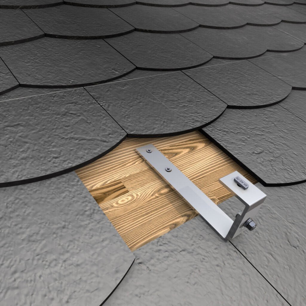
In a typical rafter-fixed tile-hook arrangement, the hook is positioned to pass through or around the roof covering and connect to the structural timber below. The tile must be accommodated without creating damaging contact or interfering with the intended drainage path.
Three different checks are therefore needed:
Structural attachment: Does the hook transfer the required loads through its fasteners into the supporting structure?
Tile clearance and protection: Can the tile sit correctly without being forced against the hook or carrying unintended concentrated loads?
Weather resistance: Does the completed roof detail maintain the intended water-shedding and weather-protection functions?
These checks are related, but they are not interchangeable. A tile can fit around a hook while the structural attachment remains inadequate. A structurally adequate connection can still leave a poorly detailed roof covering.
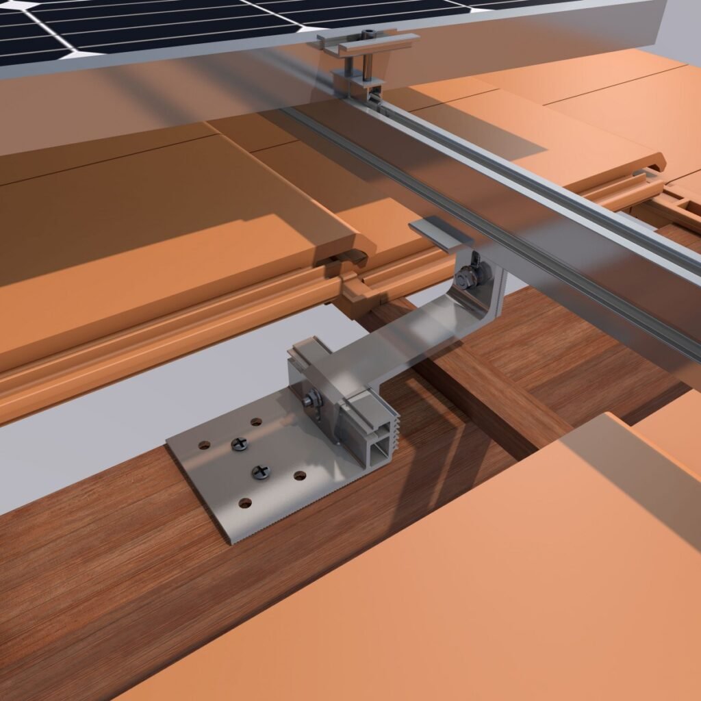
3. What governs the rafter connection?
There is no single fastener dimension or installation detail that establishes the capacity of every tile-hook connection. The relevant variables must be considered together.
Supporting timber
The timber species or engineered-wood product, relevant mechanical properties, dimensions, condition and orientation can affect connection performance.
Cracks, decay, splits, previous holes and other damage may change the suitability of the proposed fixing location. The actual support must be checked rather than assumed to match an idealized drawing.
Fastener type and geometry
Fastener diameter alone is not enough to establish connection resistance. The fastener type, thread geometry, length, material, installation method and effective engagement in the supporting member all matter.
The portion of a fastener passing through the roof covering, battens, spacers or other components should not automatically be counted as effective embedment in the structural rafter.
Use the fastener specified for the relevant mounting system unless an alternative has been properly qualified for the application.
Edge distance and member geometry
The fastener position relative to the edges and ends of the rafter matters. Insufficient edge distance or an unsuitable fastening pattern may increase splitting risk or reduce the connection’s resistance.
Roof build-ups can complicate the geometry. Counter-battens, battens, insulation and other layers may separate the visible roof surface from the structural rafter.
The fixing arrangement must account for the actual assembly, not simply the distance from the hook to the top of the roof tile.
Load direction and connection eccentricity
Wind uplift and downward loading do not necessarily produce the same governing forces or failure modes. Depending on the arrangement, the connection may also experience shear, bending or a combination of actions.
The position of the hook relative to the fasteners and rafter can introduce eccentricity. This may affect the forces in the hook and the supporting connection.
For this reason, a single pull-out result should not be treated as proof of performance under every loading condition.
Installation quality
The intended connection can only perform as qualified if it is installed within the applicable requirements.
Relevant checks include locating the actual rafter, drilling the specified pilot hole where required, using the prescribed fasteners, maintaining the specified positions and clearances, and following the manufacturer’s assembly instructions.
Do not transfer pilot-hole sizes, fastener dimensions or torque values from one product to another without supporting documentation.
4. Which failure modes should be considered?
The governing failure mode depends on the complete connection and its boundary conditions. Potential modes include:
| Component or interface | Potential concern |
|---|---|
| Tile hook | Bending or local deformation |
| Hook-to-rail connection | Slip, loosening or inadequate engagement |
| Fastener-to-timber connection | Withdrawal, shear or other connection failure |
| Timber rafter | Splitting, local damage or inadequate supporting capacity |
| Existing roof structure | Insufficient capacity or unsuitable load transfer |
| Roof tile | Cracking, point loading or interference with the hook |
| Roof covering | Water ingress due to poor clearance, flashing or drainage details |
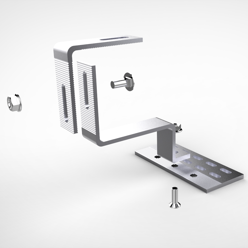
This table is a screening aid, not a prediction that any particular failure will occur.
The design should identify the relevant failure modes for the actual assembly. The weakest link in the load path can govern the result, even if the tile hook itself appears robust.
5. How should the connection be verified?
A practical assessment can be organized into three stages.
Stage 1 — Confirm the physical arrangement
Establish the tile profile, roof pitch, roof build-up, rafter location and dimensions, proposed hook model, rail system and intended fasteners.
Check whether the hook geometry permits the tile to sit correctly without forced contact or an unintended obstruction to drainage.
Stage 2 — Confirm the structural connection
Review the manufacturer’s installation instructions and any applicable engineering documentation. Confirm that the documented configuration matches the proposed installation, including the supporting member, fasteners, attachment geometry and relevant loading conditions.
Where the existing roof structure or connection capacity is uncertain, obtain the required project-specific assessment from a qualified designer.
Stage 3 — Check the complete system
Verify that the module-to-clamp, clamp-to-rail, rail-to-hook and hook-to-rafter interfaces work together. Consider the applicable project loads, support spacing, roof geometry and building structure.
Do not select the number or spacing of hooks using a generic rule of thumb when project-specific design is required.
6. What manufacturer documents can establish
Installation guides are useful for understanding how a particular manufacturer’s system is intended to be assembled. They can specify such details as fastener arrangements, rafter attachment, hook adjustment, tile clearance and installation requirements.
For example:
K2 Systems — Tile Hook 3S describes a two-piece adjustable hook and provides access to product documentation.
Clenergy — SolarRoof Pro 2.0 provides tile-roof system information and manufacturer installation guides.
IronRidge — QuickMount All Tile Hook provides product information and access to installation documentation.
These sources illustrate defined commercial systems; they do not establish that different hooks, fasteners, rails or roof conditions are interchangeable.
When reviewing a guide or test report, check the exact product, revision, fastener configuration, supporting substrate, loading direction and scope of the evidence. A test result for one defined assembly should not be transferred to another without justification.
7. Information needed for an engineering review
If a tile-hook connection needs to be selected or checked, gather the following information before requesting a capacity statement.
Roof and support
Country or project location and applicable design requirements
Tile type, profile, dimensions and roof pitch
Roof build-up, including battens, counter-battens and insulation where relevant
Rafter material, dimensions, spacing and known condition
Mounting system
Tile-hook manufacturer and model, or a dimensioned drawing
Rail manufacturer, model and connection detail
Fastener type, diameter, length and specified installation requirements
Intended hook spacing and rail span, if already established by the design
Engineering and evidence
Applicable wind, snow and other project actions
Relevant design calculations, test reports or manufacturer engineering documents
Any restrictions on the documented roof, substrate or installation configuration
The purpose is not to collect paperwork for its own sake. It is to establish whether the proposed connection and its supporting structure represent the conditions for which the engineering evidence applies.
Frequently asked questions
Does a tile hook transfer the full PV load directly into the rafter?
In a typical rafter-fixed system, the hook transfers load through its fasteners into the rafter. The complete load path continues through the roof structure, so the rafter connection cannot be assessed in isolation from the wider structure.
Can a tile hook be fixed to the roof batten instead of the rafter?
Do not assume that a batten is an acceptable substitute for a structural rafter. The intended support must match the mounting system’s approved installation and engineering basis. Clenergy’s SolarRoof Pro 2.0 documentation, for example, identifies roof rafters as the fixing location for the documented roof-hook system.
Does a stronger tile hook guarantee a stronger roof attachment?
No. The hook, fasteners, supporting timber, rail interface and roof structure have different potential failure modes. Increasing the strength of one component does not automatically increase the capacity of the complete system.
Can the required number of tile hooks be estimated from the number of modules?
Not reliably from module count alone. Hook spacing and quantity depend on the system layout, rail spans, project loads, roof geometry and supporting structure. They should be established using the applicable design method and system evidence.
If the hook fits the tile, is the installation acceptable?
Not necessarily. Physical compatibility is only one check. The structural connection, tile clearance, installation requirements and weather-protection details must also be verified.
Conclusion
A tile hook should be evaluated as part of a complete structural connection, not as an isolated metal component.
The key sequence is:
Module → clamp → rail → tile hook → fastener → rafter → roof structure.
Verify every interface against the actual roof, support, fasteners, loading conditions and applicable system documentation. Assess tile protection and weather resistance separately. Where the evidence does not match the proposed configuration, obtain a project-specific engineering review rather than relying on a generic capacity figure.