
Frameless Solar Module Clamp: Engineering Guide to Glass Clamping, Compatibility, Load and Installation
1. Start with the module, not the clamp
A frameless solar module clamp must retain the module without relying on a conventional aluminum perimeter frame. For glass-glass modules, this makes the interface between the clamp and the module particularly important: the clamp must transfer load while controlling local contact pressure, sliding, glass-damage risk and installation tolerance.
A clamp that physically fits a frameless module is not automatically qualified for that module. Before selecting a clamp, verify the exact module model, its permitted mounting method, the specified clamping zone and the clamp configuration allowed by the module manufacturer.
The selection process should follow three stages:
- Compatibility: Can the clamp, contact interface and rail physically match the module and its permitted mounting arrangement?
- Qualification: Is that configuration supported by applicable manufacturer instructions, test evidence or other relevant engineering documentation?
- Project design: Does the qualified arrangement satisfy the loads and requirements of the actual installation?
These are related questions, but they are not interchangeable.
2. What makes a frameless clamp different?
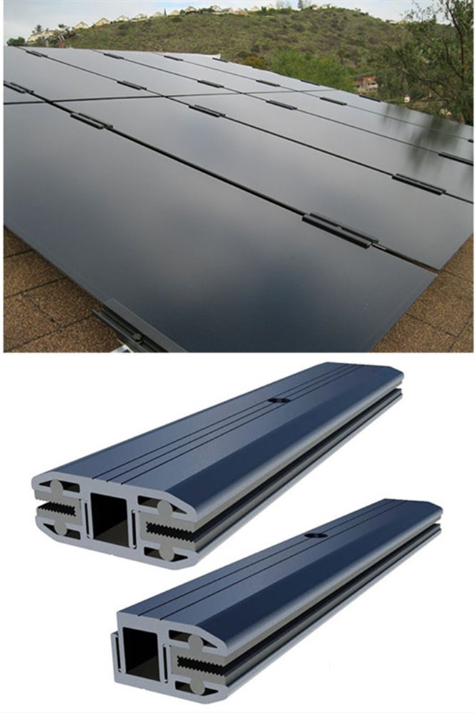
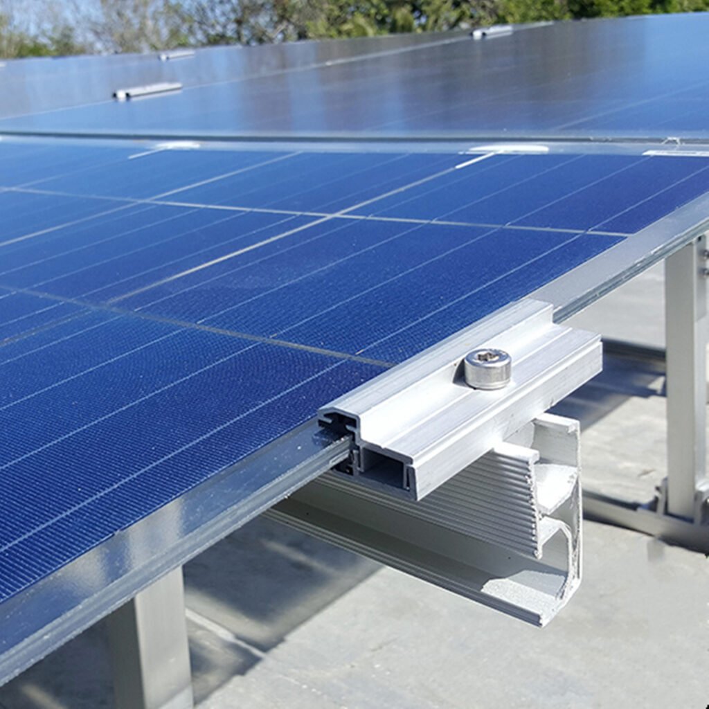
A conventional framed module clamp engages an aluminum frame. A frameless clamp may instead contact the glass or laminate through a specified compliant interface, such as EPDM or another engineered material.
That difference changes the engineering questions. The contact geometry, clamp overlap, contact pressure, installation position, rubber interface and tightening procedure may all affect whether the module is retained without damaging it.
A frameless clamp should therefore not be treated as an ordinary end clamp with the frame removed. The two arrangements have different interface conditions and may have different qualification requirements.
The module manufacturer’s instructions are the starting point. For example, Canadian Solar’s bifacial module installation manual describes a dedicated frameless mounting arrangement and specifies configuration-dependent requirements for clamp overlap, rubber and clearance. Those values apply to the stated module and mounting method; they should not be copied into a universal specification for other products.
3. Understand the complete load path
A typical frameless module retention path is:
Module glass or laminate → clamp contact interface → clamp body → fastener and hardware → mounting rail → roof or ground attachment → supporting structure
The clamp is only one part of this chain. Depending on the arrangement and loading, the governing weakness may be the glass, laminate, contact interface, clamp, bolt, rail, attachment or supporting structure.
This has two practical consequences.
First, a clamp’s material strength or dimensions do not, by themselves, establish the capacity of the complete connection. Second, a test result for one module-and-clamp assembly should not be transferred to another arrangement without checking whether the relevant configuration and boundary conditions match.
When reviewing a proposed solution, identify the full assembly rather than evaluating the clamp in isolation.
4. Check compatibility before specifying dimensions
A reliable compatibility review should cover the following interfaces.
Module construction and approved mounting method
Identify the exact manufacturer and model. Confirm whether the module is genuinely frameless, its glass construction and thickness where specified, and whether the manufacturer permits mechanical clamping at the proposed locations.
Do not assume that all glass-glass modules share the same construction or mounting requirements. If the manufacturer’s instructions do not clearly permit the proposed method, obtain clarification before proceeding.
Clamp geometry and contact area
Review the clamp drawing against the module requirements. Relevant details may include:
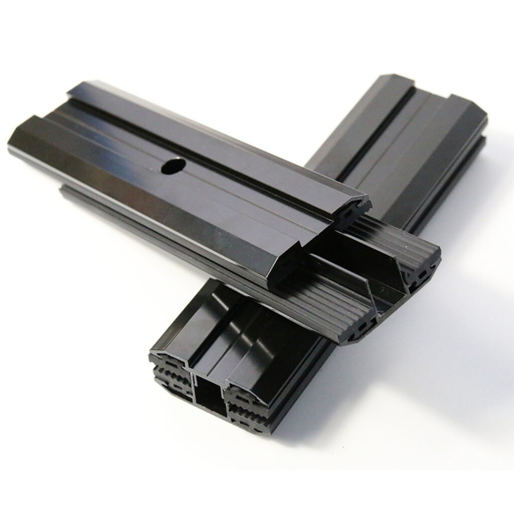
- Clamp length, shape and contact width.
- Contact location and overlap with the module.
- The geometry of the upper and lower clamp parts, where applicable.
- Edge clearances and the risk of direct contact with unintended surfaces.
- Tolerances that could change the actual contact area after installation.
A dimension that appears suitable on a drawing does not prove that the assembled interface has been qualified.
Rubber or compliant interface
Where the design requires EPDM or another compliant material, verify its specified material, thickness, location and fit. Check that it remains in the intended position during assembly and that the design does not permit unintended glass-to-metal contact.
More rubber is not automatically safer. An interface must match the intended geometry and pressure distribution; changing its thickness or hardness can change the assembled condition.
Rail and fastener interface
The clamp base must engage the intended rail correctly. Confirm the fastener type, thread, washer arrangement, available engagement and installation access. A clamp that matches the module may still be unsuitable for the rail or hardware.
Compatibility is a property of the complete interface, not just the clamp’s headline dimensions.
5. Clamp overlap, position and quantity are configuration-specific
Three recurring questions are how much the clamp should overlap the module, where it should be positioned and how many clamps are required.
There is no safe universal answer for all frameless modules.
The permitted overlap and clamp position depend on the module design and the mounting method that has been specified or qualified. Clamp quantity and spacing also need to be considered together with the module’s permitted support arrangement, rail layout and applicable load conditions.
Do not take a value from one module manual and apply it to another simply because both modules are glass-glass or have similar dimensions. For example, a manufacturer-specified overlap is evidence for that documented configuration—not a general industry rule.
Before installation, compare the proposed clamp layout with the exact module manual and the relevant mounting-system documentation. If the layout differs, obtain the required technical approval or supporting evidence rather than treating the difference as a minor installation adjustment.
6. Tightening torque and glass protection
Tightening torque is not a universal value for frameless clamps. It depends on the specified fastener and assembly, clamp geometry, interface material and the manufacturer’s installation procedure.
Excessive tightening can alter contact pressure and increase the risk of damage; insufficient or inconsistent tightening may affect retention. Neither a higher torque value nor a longer clamp automatically proves higher resistance to wind loading.
Use the torque and assembly procedure specified for the actual configuration. Do not substitute a generic torque chart for the module and clamp instructions.
Before installation, also inspect the contact surfaces and components for burrs, sharp edges, contamination, displaced rubber or damage that could create unintended stress concentrations. During installation, avoid forcing the clamp into position or bending the module to compensate for a mismatch.
If glass damage, unexpected movement or uneven contact is observed, stop and investigate the cause rather than attempting to correct it by tightening further.
7. What load can a frameless clamp support?
A standalone universal capacity value is not sufficient to specify a frameless clamp.
A meaningful capacity statement needs a defined configuration and its supporting evidence.
At minimum, review:
- Exact module model and construction.
- Clamp design, dimensions and contact interface.
- Clamp position, overlap and quantity.
- Rail, fastener and attachment arrangement.
- Load direction and the applicable test or design conditions.
- Observed failure mode and the scope of the evidence.
A pressure value quoted for a module or tested assembly is not automatically the allowable design resistance of an individual clamp. Test load, design load and complete-system capacity are different concepts.
Where a manufacturer publishes a qualified mounting arrangement, check the scope and limitations of that documentation. Where project-specific verification is required, the responsible designer needs the relevant project loads and the supporting evidence for the actual assembly.
Do not assume that a clamp is suitable for a stated wind or snow load solely because the clamp looks robust or has a large contact area.
8. Bifacial modules: check the rear-side interface too
For bifacial modules, clamp and rail placement may affect rear-side shading as well as mechanical retention. The design must satisfy the module manufacturer’s mechanical requirements without assuming that a mechanically compatible clamp is automatically optimal for energy yield.
Check the specified clamp locations, rail position and any restrictions on shading or mounting hardware. Do not alter the mounting arrangement solely to reduce shading if doing so would move the clamps outside their permitted positions or change the qualified configuration.
9. Grounding, bonding and certification
Mechanical retention and electrical bonding are separate functions. A frameless clamp should not be assumed to provide grounding or bonding unless the specific device and installation arrangement have been evaluated for that purpose.
UL Solutions’ overview of PV mounting systems certification explains that UL 2703 addresses mounting systems, mounting devices, clamping or retention devices, and grounding-related functions within its defined scope. The UL 2703 standard listing identifies the relevant standard and scope.
When evaluating a certification claim, verify the actual listing or documentation, including the identified products, module compatibility and required installation configuration. Do not interpret a reference to UL 2703 as proof that every frameless clamp is certified, universally compatible or suitable for every application.
Similarly, IEC 61215-1 concerns PV module design qualification and type approval. Module qualification does not, by itself, establish that an arbitrary clamp-and-rail arrangement is mechanically qualified.
Applicable code, structural design and electrical requirements must still be checked for the project jurisdiction and installation.
10. Evidence to request before approving a configuration
The evidence package should match the question being asked. A product catalogue may help establish dimensions, but it is not a substitute for module-specific installation instructions or assembly-level test evidence.
| Question | Useful documentation |
|---|---|
| Is the clamp permitted for this module? | Exact module installation manual or written manufacturer confirmation |
| Does the geometry match? | Module and clamp drawings, interface dimensions and tolerances |
| Is the rubber interface correct? | Material specification, thickness and assembly details |
| Is the mounting arrangement qualified? | Applicable manufacturer documentation, test report or engineering assessment |
| What load conditions are covered? | Defined configuration, load direction, test conditions and limitations |
| Does it provide bonding or grounding? | Applicable certification/listing and installation requirements |
| Is it suitable for this project? | Project loads, mounting layout and supporting design verification |
Evidence should be reviewed for applicability, not simply counted. A test report for a different module, clamp profile or rail arrangement may provide useful background, but it does not automatically qualify the proposed assembly.
11. A practical selection and qualification sequence
Use the following sequence before ordering or approving a frameless clamp.
- Identify the module. Record the manufacturer, exact model, construction and current installation manual.
- Confirm the permitted mounting method. Establish whether clamping is allowed and identify the required clamp locations.
- Check the interface. Compare the clamp geometry, overlap, contact material, rail and fastener against the documented requirements.
- Check the evidence. Confirm which module-and-clamp configuration has been tested, listed or otherwise qualified, and what that evidence actually covers.
- Verify the project. Review the applicable loads, support layout, attachment and jurisdictional requirements with the responsible designer.
- Record unresolved points. If a key dimension, approval or evidence item is missing, resolve it before treating the configuration as accepted.
This process separates a product that appears to fit from a mounting arrangement that can be justified for the intended project.
12. What to include in an RFQ for a custom frameless clamp
A useful RFQ gives the supplier enough information to assess the interface rather than quote from a product photograph alone.
Include, where available:
- Module manufacturer and exact model.
- Module drawing, glass construction and relevant thickness information.
- Installation manual and approved clamping zone.
- Required clamp position, overlap and quantity.
- Clamp and rail cross-sections or drawings.
- Fastener and rubber-interface requirements.
- Project loading and applicable design requirements.
- Required certification, testing or documentation.
- Estimated quantity, target delivery schedule and any OEM/ODM requirements.
If some information is unavailable, identify it explicitly. The supplier can then distinguish what can be checked from drawings, what requires confirmation from the module manufacturer and what may need testing or project-specific engineering.
13. Scope and limitations
This guide explains the engineering checks involved in frameless clamp selection. It does not qualify a particular clamp, module, rail or complete mounting system.
Final suitability depends on the exact module, mounting configuration, supporting evidence, project loads and applicable requirements. No universal overlap, rubber thickness, torque, clamp quantity or capacity should be inferred from this general guide.
For a configuration review or custom clamp enquiry, send the module model and drawing, installation manual, rail interface and project requirements. These inputs provide a practical starting point for a documented compatibility and qualification review.
Need to check a frameless clamp configuration?
Send us the module model and installation manual, module and clamp drawings, rail cross-section, and project requirements. We can help identify compatibility questions, documentation gaps and the information needed for further qualification.