
Solar Panel End Clamp Clamping Zone and Overlap: What Must Be Checked?
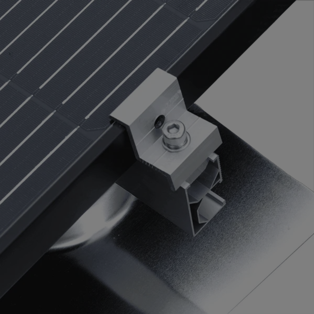
An end clamp must engage the solar module frame at an acceptable position and with the engagement specified for the relevant mounting system. Two checks are particularly important: where the clamp is allowed to contact the module frame, and how much of the frame the clamp must engage.
These requirements are related, but they are not interchangeable. A clamp may have sufficient physical reach while being positioned outside the module manufacturer’s permitted clamping zone. It may also sit within the permitted zone without achieving the required overlap or engagement.
Neither condition should be accepted on appearance alone.
The correct installation must satisfy the applicable module instructions and mounting-system requirements for the actual configuration.
1. What Is the Module Clamping Zone?
The clamping zone is the part of the module frame, or the specified range of mounting positions, within which the module manufacturer permits the module to be supported or clamped under the stated conditions.
It is not necessarily the entire length of the frame.
Module installation manuals may define permitted clamp positions, support locations or mounting ranges. These instructions can be linked to the module’s structural qualification and the mounting configuration used for the stated mechanical-load conditions.
For an end clamp, the first question is therefore not simply whether the clamp can reach the frame. It is whether the intended contact position complies with the instructions for the exact module model. Before installation, identify:
The module manufacturer and exact model.
The applicable installation manual and revision.
The permitted clamping or support positions.
Any specified mounting configuration or restrictions.
The relevant frame dimensions and clamp engagement requirements.
Do not assume that instructions for another module in the same product family apply without checking the documentation.
2. What Does Clamp Overlap or Engagement Mean?
Overlap describes how the clamp’s contact portion engages the module frame. The exact geometry depends on the clamp design and the frame profile.
For a conventional framed module, the clamp must contact the intended frame surface in the manner specified by the mounting-system design. The engagement must be sufficient to achieve the intended interface—not merely enough for the clamp to appear seated.
The relevant dimensions may include:
The clamp’s contact or gripping length.
The module frame’s flange geometry.
The clamp’s position relative to the frame edge.
The clamp’s height and contact profile.
The installation clearances and orientation specified for the system.
The manufacturer’s terminology matters. A manual may specify clamp overlap, minimum grip length, clamp dimensions or a defined contact arrangement. These terms should be interpreted within that document rather than treated as universally interchangeable measurements.
Do not invent a minimum overlap dimension when the applicable manufacturer documentation does not provide one.
If a supplier proposes a clamp for which the required engagement is unclear, request the dimensional drawing and installation requirements before approving the interface.
3. Why Clamping Position and Overlap Must Be Checked Together
Clamping position and overlap address different aspects of the interface.
Position establishes whether the clamp is located within the module manufacturer’s permitted mounting region.
Overlap or engagement establishes whether the clamp contacts and retains the frame as required by the relevant design.
A correct position does not automatically prove adequate engagement. Adequate-looking engagement does not make an otherwise prohibited position acceptable.
Consider three situations:
| Situation | What can be concluded? | What remains to be checked? |
|---|---|---|
| The clamp sits within the permitted zone and appears to engage the frame | The initial geometric check may be satisfactory | Confirm specified dimensions, installation details and applicable system requirements |
| The clamp engages the frame but sits outside the permitted zone | Physical contact alone does not establish acceptability | Resolve the position against the module manufacturer’s instructions |
| The clamp sits within the permitted zone but has uncertain or incomplete engagement | The position alone is insufficient | Verify clamp geometry, overlap and installation against the applicable documents |
These are interface checks, not a substitute for structural qualification. Where the proposed arrangement differs from the documented configuration, additional clarification or engineering validation may be required.
4. How These Requirements Relate to Module Mechanical-Load Qualification
Module mechanical performance is tied to defined support and clamping configurations. A module’s qualification or published load information should not be interpreted as approval for any arbitrary clamp position or engagement geometry.
The REC module installation documentation, for example, connects mounting configuration and clamp location with the conditions under which stated load values apply. Canadian Solar’s installation manual also addresses defined clamping positions, clamp dimensions and overlap requirements.
These manufacturer documents support an important distinction:
A module’s stated mechanical-load performance cannot automatically be transferred to a different mounting arrangement without checking whether the relevant conditions remain applicable.
The following changes should trigger a review rather than an assumption of equivalence:
Moving the clamp to a different position.
Changing the clamp’s engagement geometry.
Using a different module frame profile.
Changing the rail or mounting arrangement.
Proposing a configuration not covered by the applicable installation instructions.
The consequences depend on the specific module and system. It would be incorrect to assign a universal capacity reduction or a single failure threshold to every change in clamp position or overlap.
5. How to Verify an End Clamp Before Installation
Use the following sequence to review the proposed interface.
Step 1 — Identify the exact module
Record the module manufacturer, model and applicable installation-manual revision. Do not rely only on wattage, external dimensions or a general product-family name.
Step 2 — Locate the permitted clamping positions
Find the relevant installation drawing or table. Determine whether the manual specifies a range, a distance from a reference point, or a particular mounting arrangement.
If the intended end-clamp location cannot be matched confidently to the instructions, ask the module manufacturer or responsible system designer for clarification.
Step 3 — Confirm the required engagement
Check whether the documentation specifies minimum overlap, grip length, clamp dimensions or another engagement condition.
Use the defined measurement and reference surfaces in the relevant document. Do not substitute a visual estimate for a stated dimensional requirement.
Step 4 — Check the actual clamp and rail geometry
Use the end-clamp drawing and the rail-system documentation to confirm the intended contact surfaces, clamp orientation and fastening interface.
For a custom clamp, a drawing comparison may identify dimensional conflicts, but it does not by itself prove structural suitability.
Step 5 — Verify installation conditions
Check the mounting-system instructions for positioning, fastening sequence, rail-end or rail-joint clearance where applicable, and the specified tightening procedure.
Torque values and installation details must come from the applicable product instructions. Do not transfer them from another clamp system.
Step 6 — Resolve any undocumented configuration
If the proposed combination falls outside the stated instructions, do not treat successful assembly as approval. Obtain written clarification or appropriate engineering validation before relying on the arrangement.
6. What Should Be Recorded for Engineering Review?
For a project-specific compatibility check, retain enough information for another engineer to reproduce the decision.
| Item | Evidence to retain |
|---|---|
| Module identity | Manufacturer, exact model and manual revision |
| Permitted mounting position | Relevant manual page, drawing or table |
| Frame geometry | Frame drawing or dimensions needed for the interface |
| End clamp | Exact model and dimensional drawing |
| Engagement | Manufacturer-specified overlap, grip length or equivalent requirement |
| Rail interface | Rail model and relevant cross-section or interface drawing |
| Installation conditions | Applicable installation instructions and required fastening details |
| Unresolved issues | Any deviation, missing dimension or manufacturer clarification |
This record helps distinguish a documented compatibility check from an informal judgement that the clamp appears to fit.
7. What If the Clamp Is Custom or the Module Is Not Listed?
A custom end clamp may be feasible even when a standard compatibility list does not cover the proposed module. However, customization should begin with the interface requirements—not with an assumed frame-height match.
At minimum, obtain the module frame drawing, permitted clamping zone, relevant engagement requirements and rail interface details. Compare the proposed geometry with the manufacturer’s instructions.
If the configuration is not covered by the available documentation, determine what additional review is needed. Depending on the application, this may include manufacturer confirmation, prototype fit checks and engineering validation of the relevant assembly.
A successful fit check establishes only what was actually checked. It does not independently establish the load capacity of the complete module–clamp–rail system.
FAQ
Can I move an end clamp outside the module’s specified clamping zone if it has enough overlap?
Do not assume this is acceptable. Adequate physical engagement does not override the module manufacturer’s mounting requirements. Any proposed deviation needs appropriate clarification or engineering approval.
Is more overlap always better?
Not as a universal rule. The relevant requirement is the engagement geometry specified for the clamp and module interface. Increasing overlap does not automatically make an installation compliant, and the clamp must still be positioned and installed as required.
Is there a universal minimum end-clamp overlap?
No universal value should be applied to every framed module and end-clamp design. Use the applicable module and mounting-system documentation. If the requirement is missing or ambiguous, obtain clarification rather than inventing a dimension.
Does a clamp that passes a visual inspection prove that the module is properly supported?
No. A visual check may identify obvious misalignment or incomplete engagement, but it does not establish compliance with the specified clamping zone, dimensional requirements or structural qualification conditions.
Does IEC 61215 define the overlap required for every end clamp?
IEC 61215 is a PV-module design qualification and type-approval framework, not a universal dimensional specification for all end clamps. The actual clamping requirements must be established from the relevant module and mounting-system documentation.
Conclusion
End-clamp selection and installation require two distinct checks: the clamp must be positioned within the applicable module clamping zone, and its engagement with the frame must satisfy the relevant dimensional and installation requirements.
Neither position nor overlap should be judged in isolation. Both must be assessed against the exact module and mounting-system documentation, with any undocumented configuration resolved before installation.
The engineering objective is not simply to make the clamp fit. It is to establish that the proposed interface follows the applicable requirements and that the evidence supports the intended use.
Technical References
Canadian Solar — PV Module Installation Manual — manufacturer documentation covering clamping positions, clamp dimensions and overlap requirements.
REC Group — PV Module Installation Manual — mounting configurations, clamp location and grip-length conditions associated with stated module load values.
IEC — IEC 61215-1 — PV-module design qualification and type-approval framework.
IEC — IEC 61215-2 — PV-module test procedures.
Use the latest applicable manual for the exact module and mounting-system models. Manufacturer instructions and approved configurations may vary by product and revision.
Need to check an end clamp against your module?
Send us the module model, frame drawing, installation manual and rail details for an initial compatibility review.