
How to Choose the Right Solar Panel End Clamp for a Module Frame
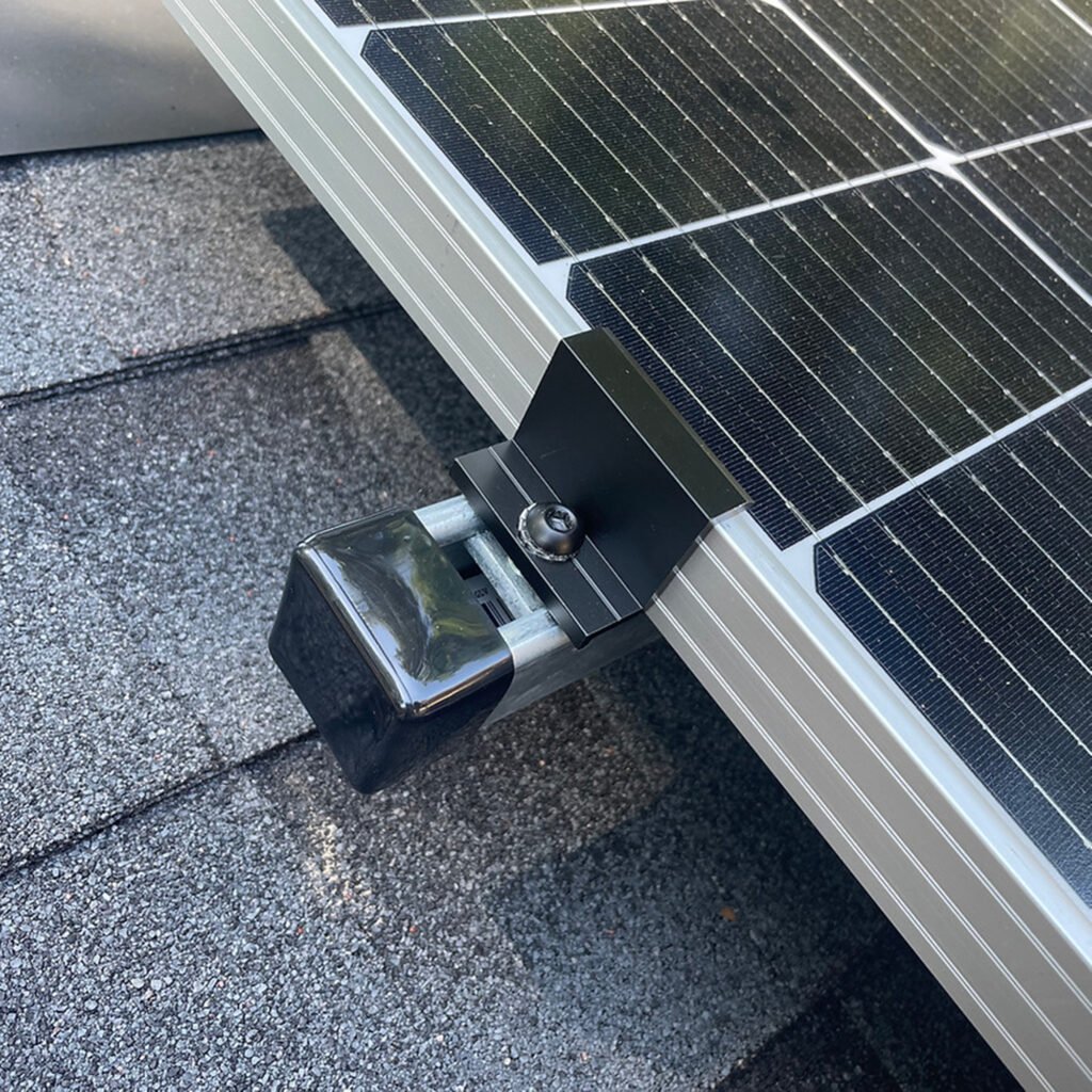
Choosing a solar panel end clamp is not simply a matter of matching the clamp height to the module frame height. The clamp must engage the frame correctly, fit the mounting rail, and remain within the module manufacturer’s permitted mounting conditions.
A clamp may appear to fit a module but still be unsuitable for the intended installation. Frame geometry, clamping position, engagement, rail interface and system requirements all affect the decision.
The practical rule is to verify the module, clamp and rail as one interface—not to select a clamp by frame height alone.
1. Start With the Exact Solar Module
Before selecting an end clamp, identify the module manufacturer and exact model.
Two modules with the same nominal frame height may have different frame profiles, flange dimensions or approved mounting positions. Their compatibility with a particular clamp should not be assumed to be identical.
Obtain the module manufacturer’s current installation manual and, where necessary, a frame drawing. Confirm:
Module manufacturer and model
Frame height
Frame cross-section and relevant flange geometry
Permitted clamping zones
Required clamp engagement or overlap
Applicable installation and mounting restrictions
Module wattage and overall panel dimensions are not enough to establish clamp compatibility. The frame interface and mounting requirements are more directly relevant.
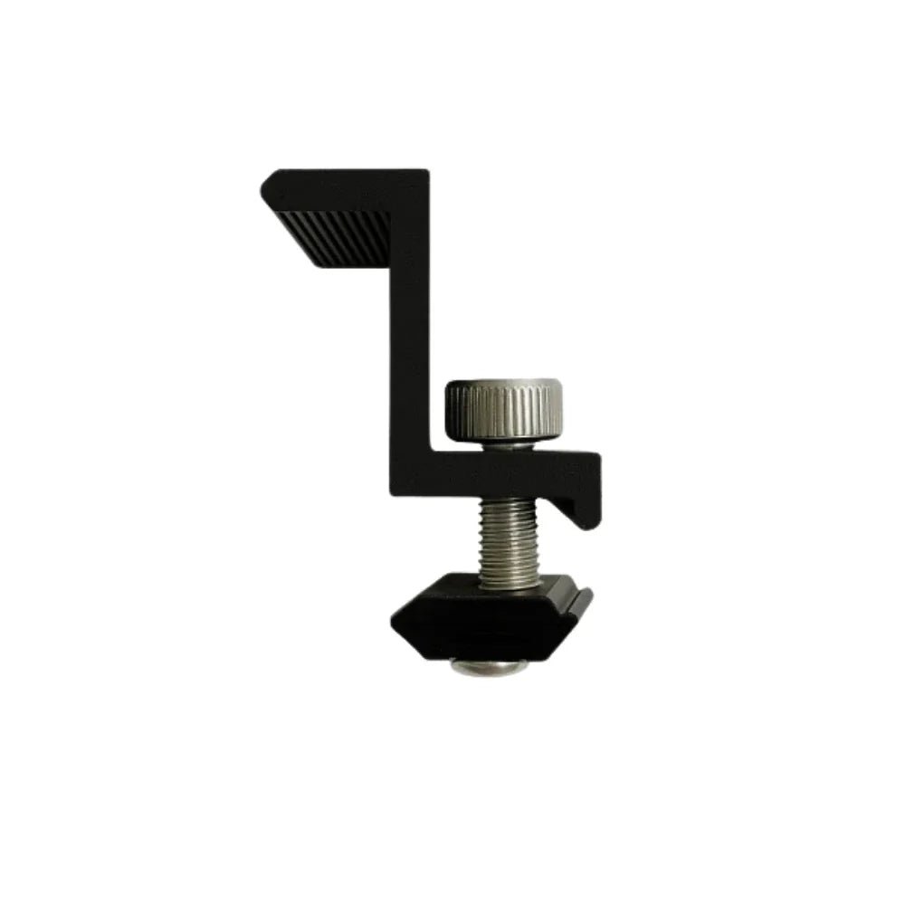
2. Check Frame Height—but Do Not Stop There
Frame height is an important initial screening dimension because the clamp must reach and engage the frame as intended.
However, the nominal height does not describe the entire frame profile. Depending on the clamp design, other dimensions may determine whether the clamp can be installed correctly.
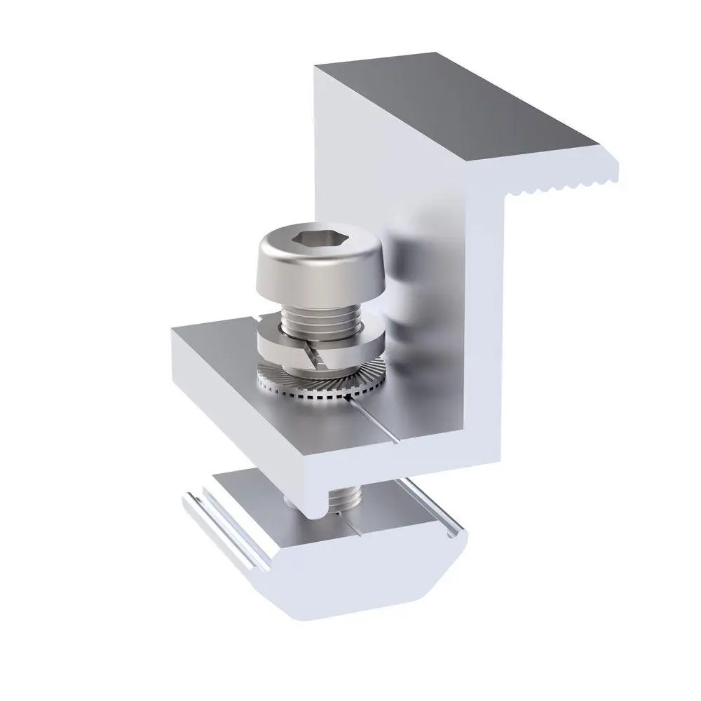
For example, a conventional visible end clamp and a hidden end clamp may engage the module frame in different ways. A hidden design may require a particular return-flange shape, minimum flange length or frame thickness.
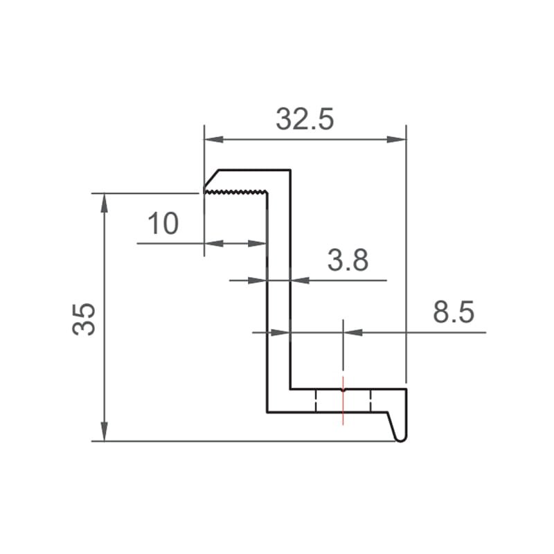
A useful initial check is:
| Check | What to confirm |
|---|---|
| Frame height | Is the module within the clamp manufacturer’s stated dimensional range? |
| Frame thickness | Does the clamp accommodate the relevant frame section? |
| Return flange | Is the flange geometry compatible with the clamp’s engagement mechanism? |
| Clamp engagement | Can the clamp contact and retain the frame as designed? |
| Clamp position | Can it be installed within the module manufacturer’s permitted clamping zone? |
| Rail interface | Does the clamp fit the intended rail and fastening arrangement? |
Not every clamp design requires every check in the same way. The manufacturer’s instructions determine which dimensions and conditions apply to the specific product.
3. Verify the Module Manufacturer’s Clamping Zone
A clamp that physically fits the frame is not automatically acceptable for structural use.
PV module manufacturers commonly specify where the module may be supported or clamped. These permitted positions may depend on the module design and the mounting configuration used for mechanical-load qualification.
Before approving an end clamp, check:
Where the module manufacturer permits clamping.
Whether the proposed end-clamp position falls within that permitted area.
Whether the clamp provides the required engagement and overlap.
Whether the installation follows the module manufacturer’s mounting instructions.
Whether any mounting restrictions apply to the specific module model.
Do not assume that a clamp can be moved to any convenient point along the frame. Nor should a clamp’s own dimensional range be treated as proof that every module within that range is approved for the installation.
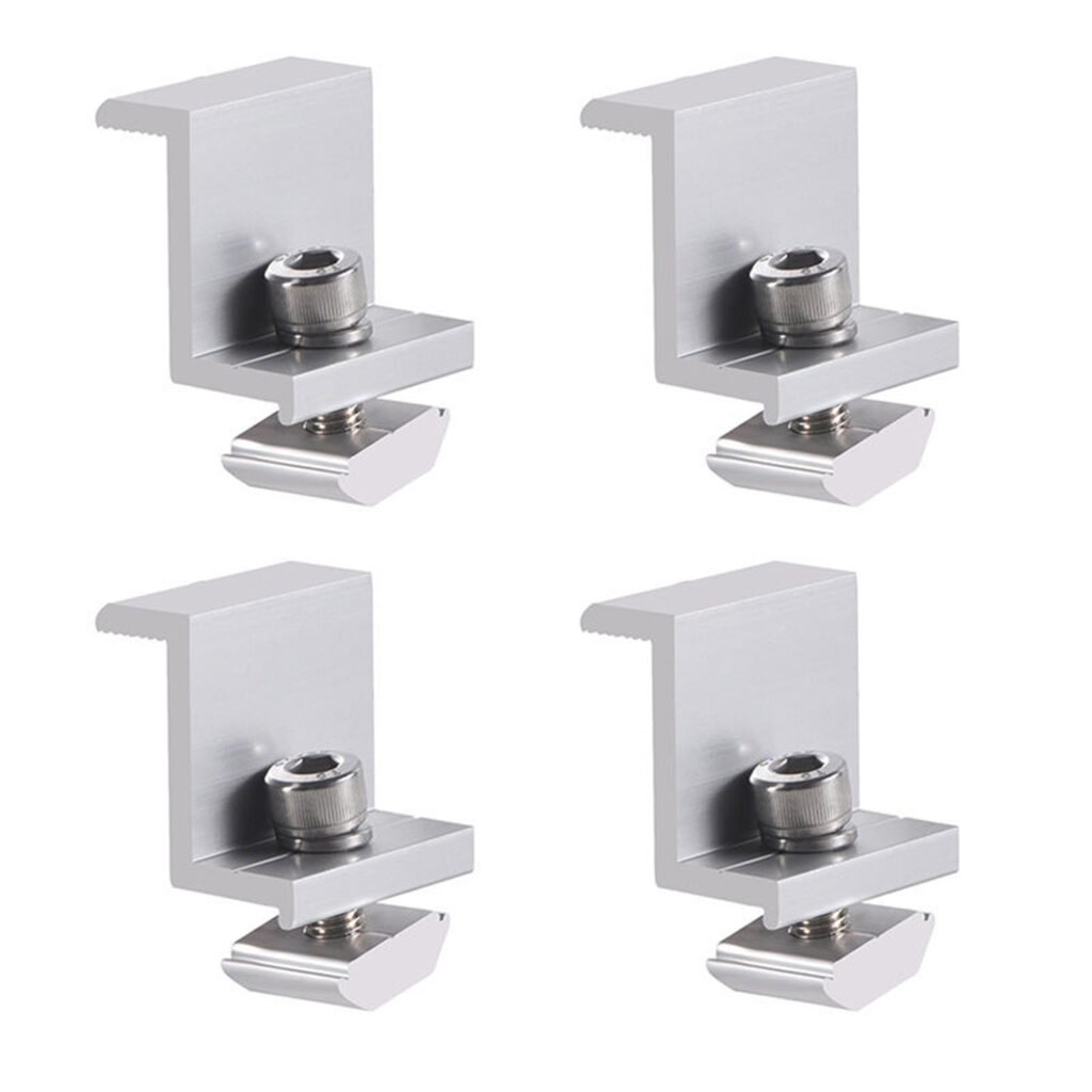
If the module manual does not clearly cover the proposed arrangement, obtain clarification from the module manufacturer or the responsible system designer.
4. Check the Clamp-to-Rail Interface
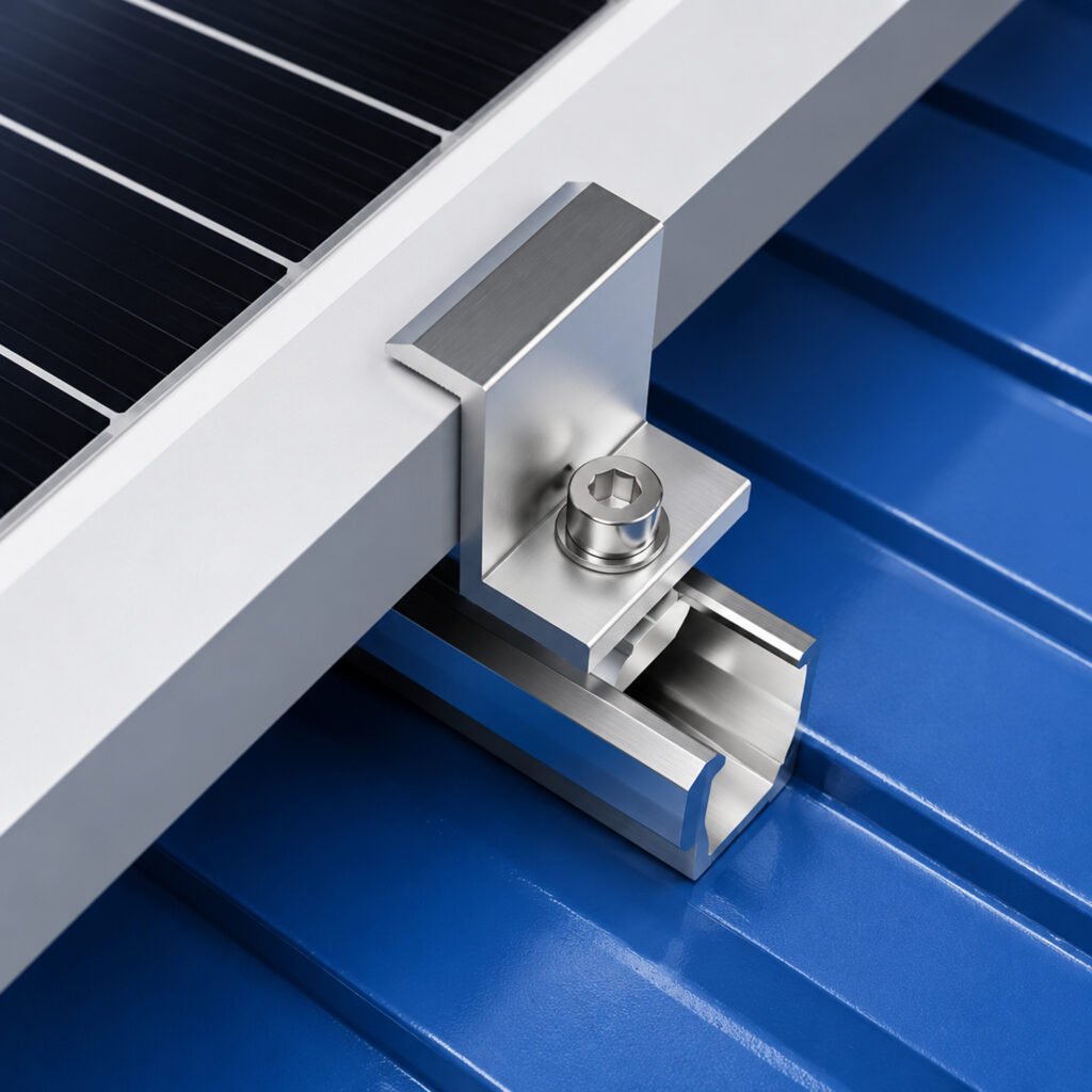
End-clamp selection also depends on the mounting rail. The clamp must connect to the rail using the intended fastening arrangement and be installed in the specified orientation.
Check the following:
Rail manufacturer and model
Rail top-channel or clamp interface geometry
T-bolt, rail nut or other fastening arrangement
Clamp orientation and installation sequence
Position restrictions near rail ends or rail joints
Required tightening procedure and product-specific torque, where specified
A clamp that fits the module frame may still be incompatible with the rail. Likewise, a clamp that can be physically attached to a rail is not necessarily qualified for the complete module-and-rail combination.
Avoid mixing components from different mounting systems unless their compatibility and performance have been appropriately established.
5. Understand What a Manufacturer’s Compatibility Range Means
Some mounting-system manufacturers publish a frame-height range for a particular clamp family. Such a range is useful for screening potential applications, but its meaning must remain within the manufacturer’s stated product and system scope.
For example, Schletter’s ProLine product information describes a clamp range covering module frame heights of 30–47 mm for the referenced system. This is evidence of a manufacturer-defined range for that product family—not proof that every clamp can fit every module in that range.
A stated range should prompt further checks:
Does the range apply to the exact clamp model being offered?
Is the intended rail included in the documented system?
Are there frame-shape or flange restrictions?
Does the module manufacturer’s installation manual permit the proposed clamping arrangement?
Are any structural, bonding or certification requirements relevant to the project?
A dimensional range is a compatibility statement, not a universal structural qualification.
6. Separate Physical Fit From Engineering Qualification
End-clamp selection involves more than one decision.
Stage 1 — Physical compatibility
Can the clamp engage the frame correctly and connect to the intended rail?
This stage considers dimensions, geometry, engagement, overlap and fastening interfaces.
Stage 2 — Installation compatibility
Can the clamp be installed according to both the mounting-system instructions and the module manufacturer’s requirements?
This includes permitted clamping position, installation orientation and product-specific tightening instructions.
Stage 3 — Engineering and project qualification
Is the proposed configuration appropriate for the project requirements and any applicable certification or listing conditions?
Where structural performance is relevant, the module, clamp, rail and supporting attachments form a connected load path. A clamp’s product specification alone does not establish the capacity of the complete mounting system.
If grounding or bonding is required, verify that functionality separately. Mechanical retention and electrical bonding are related system considerations, but they are not interchangeable claims.
Passing one stage does not automatically establish the next.
7. What to Request From a Supplier
If you are evaluating an end clamp for a specific project, provide enough information for the supplier to assess the actual interfaces.
Module information
Module manufacturer and exact model
Frame height and cross-section drawing
Frame thickness and return-flange dimensions, where relevant
Module installation manual
Approved clamping zone and any mounting restrictions
Mounting-system information
Rail manufacturer and model
Rail interface drawing, if available
Required clamp type and installation orientation
Fastener or rail-nut arrangement
Relevant installation instructions
Project requirements
Project country and applicable requirements
Module arrangement and mounting configuration
Structural design requirements
Any required certification, listing or bonding functionality
Expected quantity and whether a standard or custom clamp is being considered
A frame drawing or CAD file can help confirm dimensional interfaces. It does not, by itself, establish structural capacity or manufacturer approval.
If the proposed clamp is a custom design, the review may need to extend beyond dimensional matching to prototype checks, installation verification and suitable engineering validation.
8. Common End-Clamp Selection Mistakes
Selecting by frame height alone.
A nominal height match does not establish compatibility with the complete frame profile, clamping zone or rail.
Assuming all modules with the same frame height are equivalent.
Different frame cross-sections and manufacturer requirements may affect engagement and installation.
Treating a clamp’s stated range as universal approval.
A published range applies to the specified product and documented conditions.
Ignoring the module installation manual.
The module manufacturer’s permitted clamping positions and mounting restrictions remain important even when the clamp appears to fit.
Mixing clamp and rail systems without verification.
The fastening interface and intended installation arrangement must be compatible.
Assuming a physical fit proves structural capacity.
Structural suitability depends on the relevant configuration and supporting evidence, not appearance alone.
FAQ
Can one end clamp fit different solar panel frame heights?
Some clamp designs are intended to cover a stated range of frame heights. Whether one clamp is suitable for multiple modules depends on its documented geometry, rail interface and the requirements of each module. A common height range alone is not sufficient proof.
Is frame height the most important end-clamp dimension?
It is an important starting point, but not the only one. Frame thickness, flange geometry, clamp engagement, permitted clamping position and rail compatibility may also matter, depending on the design.
If an end clamp fits the frame, can I use it?
Not on physical fit alone. Check the module manufacturer’s installation requirements, the clamp and rail instructions, and any applicable engineering or certification requirements.
Do I need a module frame drawing to select an end clamp?
Not in every straightforward case. The exact module model and its current installation manual may provide sufficient information for a documented standard configuration. A frame drawing is useful when the geometry is unclear, a hidden clamp is involved, or a custom interface is being developed.
Does a module’s IEC 61215 qualification prove that any end clamp can be used?
No. IEC 61215 is a PV-module qualification framework; it does not automatically qualify every third-party clamp or mounting configuration. Verify the actual module mounting instructions and the evidence relevant to the proposed system.
Conclusion
The right solar panel end clamp is not simply the one with a matching height. It must engage the specific module frame correctly, fit the intended rail, comply with the module manufacturer’s mounting requirements and meet the project’s applicable qualification needs.
For reliable selection, start with the exact module model and installation manual. Verify the frame geometry and permitted clamping zone, check the rail interface, and distinguish physical compatibility from structural approval.
When the standard documentation does not clearly cover the proposed combination, resolve that gap before ordering or installing the clamp.
Technical References
Canadian Solar — PV Module Installation Manual — module clamping positions, clamp dimensions and installation requirements.
Unirac — NXT / UMount Installation Guide — hidden end-clamp geometry and module-frame engagement requirements.
Schletter Group — ProLine US — example of a manufacturer-defined module frame-height range within a specific mounting-system family.
IronRidge — Eclipse XR Hidden End Clamp — example of a clamp designed for a specific rail system and interface.
K2 Systems — Product and Installation Resources — end-clamp installation and mounting-system requirements.
Always use the latest applicable documentation for the exact module and mounting-system models. Product configurations and manufacturer instructions may change.
Need help checking compatibility?
Send us your module model or frame drawing, rail model and installation requirements.