
L Foot to Rail Connection: How to Check Solar Mounting Rail Compatibility
A solar L Foot connects a mounting rail to a roof attachment. The connection is commonly made with a T-bolt and nut, but the fact that a T-bolt can enter a rail slot does not prove that the combination is mechanically compatible or approved for use.
The connection must match the rail profile, slot geometry, T-bolt dimensions, bolt-head engagement, hardware arrangement and installation requirements. The permitted position and tightening procedure may also be specific to the mounting system.
Physical fit is not the same as engineering qualification.
This guide explains what to check when selecting or installing an L Foot-to-rail connection, and what information is needed before combining components from different manufacturers.
1. How does an L Foot connect to a solar rail?
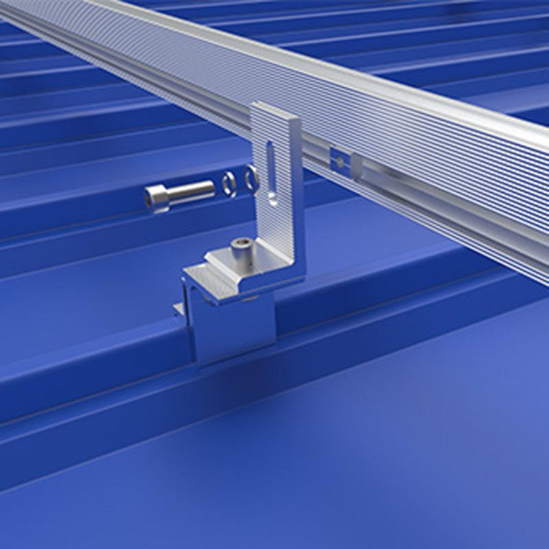
In a typical arrangement, the L Foot is fixed to a roof attachment or supporting structure. A T-bolt connects the upper part of the L Foot to the mounting rail.

The connection can be understood as:
Roof attachment → L Foot → T-bolt and nut → rail channel
The T-bolt head engages inside the rail channel. The threaded portion passes through the L Foot slot or mounting hole, where a nut secures the assembly.
This arrangement allows the rail to be positioned and adjusted during installation. However, the final connection must provide the engagement and restraint intended by the system design.
The exact hardware arrangement varies between manufacturers. Some systems use a slotted L Foot and a separate T-bolt; others use proprietary rail fasteners or integrated attachment components.
Do not assume that visually similar parts use the same connection geometry.
2. What determines L Foot and rail compatibility?
Compatibility is not determined by one dimension. The following interfaces should be checked together.
Rail profile and channel geometry
Start with the exact rail manufacturer and model.
Relevant dimensions and features include:
Rail cross-section and channel shape
Internal channel width and height
Slot opening and entry geometry
Channel lips or retaining features
Available space for the T-bolt head
Rail-end access and permitted insertion method
Two rails may look similar from the outside but have different internal channel dimensions.
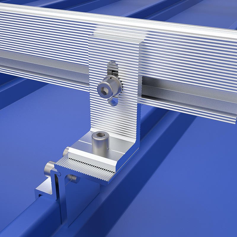
A T-bolt that enters one rail may not seat correctly in another. Even when it can be inserted, the bolt head may not achieve the required engagement with the channel.
For this reason, a generic description such as “40 mm solar rail” is not enough to confirm compatibility.
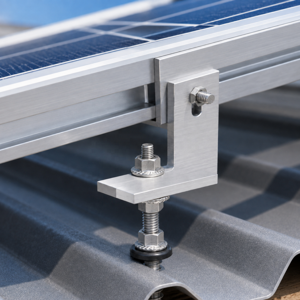
T-bolt dimensions and head geometry
Check the complete T-bolt, not just its thread diameter.
Important details include:
Thread diameter and pitch
Bolt length and usable thread length
Head width, length and thickness
Head shape and corner geometry
Washer and nut arrangement
Position indicator, where provided
Material and corrosion protection
The bolt head must engage with the rail channel as intended. The nut and threaded portion must also suit the L Foot thickness and the specified hardware arrangement.
A matching thread diameter does not establish that the bolt head is suitable for the rail.
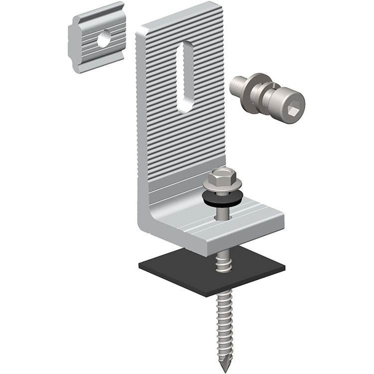
L Foot slot or mounting-hole geometry
The L Foot must accommodate the specified T-bolt and allow the intended assembly position. Check:
Slot width and length, or hole diameter
Material thickness around the slot
Available adjustment range
Permitted T-bolt position
Clearance for the nut and washer
Whether the bolt can be installed and tightened without interference
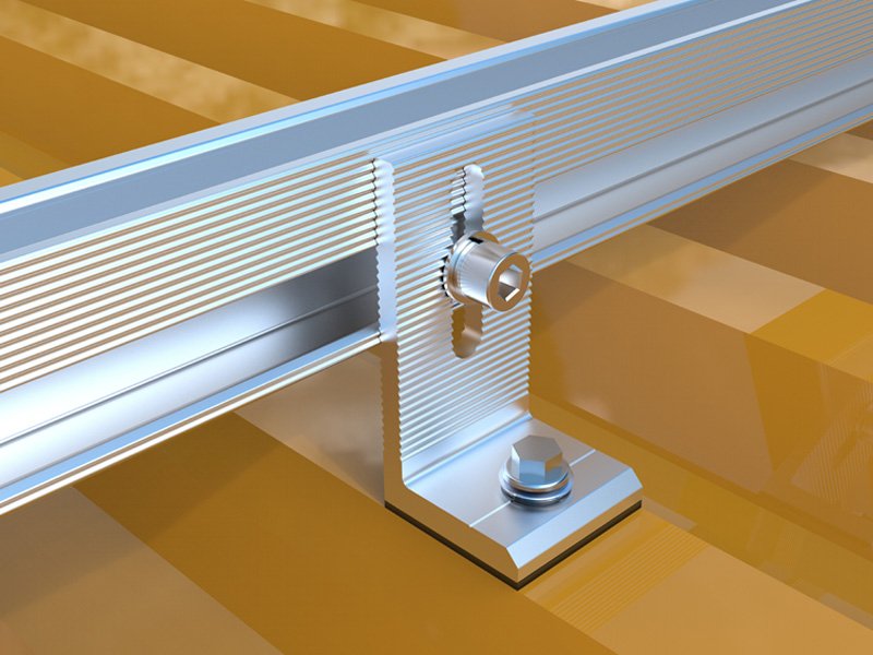
A longer slot may provide more adjustment, but it does not automatically improve the structural performance of the connection. The actual bolt position and permitted installation range remain part of the design.
Hardware arrangement
The nut, washer and any specified locking or bonding hardware form part of the connection.
Do not replace supplied hardware based only on matching thread size. A different nut, washer or bolt may change the contact geometry, engagement, tightening behavior or electrical bonding arrangement.
If a replacement is necessary, confirm that it is approved for the intended rail and L Foot combination.
3. Why T-bolt engagement matters
The T-bolt head must engage correctly with the retaining surfaces inside the rail channel.
If the head is not correctly positioned, the connection may not behave as intended when the nut is tightened or when the assembly is loaded.
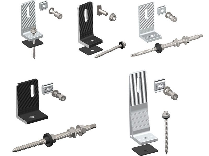
Potential installation problems include:
T-bolt head not fully rotated into its intended position
Bolt head not seated against the channel retaining surfaces
Incorrect bolt orientation
Insufficient engagement due to incompatible dimensions
Rail or L Foot misalignment
Hardware interference that prevents correct tightening
The installation indicator, where provided, can help confirm the bolt’s orientation. It should be interpreted according to the relevant manufacturer’s instructions rather than treated as a universal indicator design.
For example, IronRidge’s QRail installation documentation specifies a particular T-bolt orientation and an engagement indication line. The guide describes the required alignment for that system. It should not be transferred automatically to other rail profiles or T-bolts.
See the manufacturer’s QRail system documentation.
4. Does a T-bolt that fits the rail mean the connection is approved?
No. A physical fit check answers whether the parts can be assembled. It does not establish whether the assembly has been qualified for the intended mechanical or electrical function.
A proper compatibility review should distinguish three levels:
Level 1 — Physical fit
Can the T-bolt enter the rail? Can the bolt head rotate or slide into position? Can the L Foot and rail be assembled without interference?
Level 2 — Correct mechanical engagement
Does the bolt head engage with the rail channel as intended? Are the bolt, nut, washer and L Foot geometry consistent with the specified arrangement? Can the required tightening procedure be followed?
Level 3 — System qualification
Is this combination included in the manufacturer’s approved system configuration, or supported by appropriate engineering evidence for the intended application?
A combination may pass the first check and still fail the second or third.
If components from different manufacturers are being combined, request written compatibility confirmation or supporting engineering evidence. Do not treat a successful trial assembly as proof of structural suitability.
5. T-bolt orientation and installation position
The correct T-bolt orientation depends on the rail and fastener design.
Some systems use a position indicator to show the direction of the bolt head. Others provide a specific installation diagram or a visual check.
The installer should follow the relevant system instructions for:
Bolt insertion and rotation
Head engagement
Rail positioning
L Foot alignment
Nut and washer installation
Final tightening sequence
Rail-end position may also be controlled. Some systems specify a minimum distance between the T-bolt and the end of the rail, or require a defined amount of rail engagement.
These requirements should not be replaced by visual judgment.
A manufacturer-specific example
IronRidge’s QRail installation documentation describes the T-bolt facing a specified direction during initial positioning. It also explains how to confirm full engagement using the indication line and provides a defined rail-end clearance requirement.
These are instructions for the documented QRail configuration, not universal dimensions for every solar rail.
6. What torque should be used for an L Foot-to-rail connection?
Use the torque specified by the manufacturer for the exact hardware and system configuration.
There is no single universal L Foot-to-rail torque.
The required value may depend on:
T-bolt diameter and material
Nut and washer design
Thread condition
Lubrication or anti-seize requirements
Rail channel geometry
L Foot design
Manufacturer’s installation procedure
The effect of lubrication is particularly important. Applying anti-seize can change the relationship between tightening torque and bolt preload. It should only be used where the relevant instructions specify it.
For example, the Unirac SolarMount installation guide identifies its own L Foot-to-rail hardware and provides a system-specific tightening requirement. That value should not be used for an unrelated T-bolt or rail.
See the Unirac SolarMount Installation Guide.
Do not copy a torque value from another manufacturer’s manual simply because the thread diameter appears to be the same.
Torque is an installation requirement. It is not, by itself, a structural capacity rating.
7. Does the L Foot-to-rail connection provide electrical bonding?
Not automatically.
Mechanical fastening and electrical bonding are separate requirements.
Some mounting systems use specified T-bolts, serrated flange nuts or other qualified hardware to provide an electrical bonding path between the rail and L Foot.
Other combinations may provide mechanical attachment without being qualified for that electrical function.
Before making a bonding claim, confirm:
Whether the system is designed to provide bonding at this interface
Which bolt, nut, washer or bonding component is required
Whether surface treatments or coatings affect the intended contact
Whether the complete configuration is covered by the relevant test or listing
Whether the installation instructions require additional bonding components
A metal-to-metal connection alone is not sufficient evidence of a qualified bonding path.
Keep grounding and bonding statements within the scope of the tested or listed system.
8. Can I use an L Foot from one manufacturer with a rail from another?
Do not assume cross-brand compatibility.
The L Foot may have a suitable slot and the T-bolt may appear to fit the rail, but the complete combination still needs to be checked.
At minimum, compare:
| Interface | What to verify |
|---|---|
| Rail channel | Internal dimensions, slot geometry and retaining surfaces |
| T-bolt head | Width, length, thickness and engagement |
| Thread | Diameter, pitch and usable length |
| L Foot | Slot or hole geometry, thickness and permitted position |
| Nut and washer | Correct hardware type and contact arrangement |
| Installation | Orientation, engagement and specified torque |
| System qualification | Manufacturer approval or appropriate engineering evidence |
| Bonding | Whether the exact hardware combination is qualified for bonding |
Where the proposed combination is not covered by the manufacturer’s documentation, request written confirmation before specifying it for a project.
For OEM or custom applications, a dimensioned drawing and controlled sample assembly can help establish physical compatibility. Structural and bonding qualification still require their own evidence.
9. Information needed to check an L Foot and rail combination
To review a proposed connection, provide:
Rail information
Manufacturer and model
Rail cross-section drawing or dimensions
Channel opening and internal geometry
Rail material and finish
L Foot information
Manufacturer and model
Overall dimensions and thickness
Slot or hole dimensions
Material and surface treatment
Available adjustment range
T-bolt and hardware
Thread diameter and pitch
Bolt length and head dimensions
Nut and washer specifications
Material and finish
Position indicator or installation drawing, if available
Application
Roof attachment type
Intended rail orientation and position
Required mechanical function
Bonding requirements, if applicable
Project location and relevant design requirements
For a cross-brand combination, include the original manufacturer manuals or written approval where available.
Frequently asked questions
Can I use any T-bolt that matches the rail slot?
No. Thread size and physical insertion are not enough. The bolt head geometry, engagement, orientation, hardware arrangement and system qualification must also be checked.
Does a wider T-bolt head always provide better engagement?
Not necessarily. The head must match the channel geometry and be capable of reaching the intended seated position. A larger head may not fit or rotate correctly. Use the specified bolt or obtain engineering confirmation for an alternative.
Can I use a longer T-bolt?
A longer bolt is not automatically a better choice. It must suit the L Foot thickness, nut engagement, available clearance and intended hardware arrangement. Follow the manufacturer’s specified hardware requirements.
Is the torque the same for all L Feet?
No. Torque depends on the specified fastener and system. Values from one manufacturer’s instructions should not be transferred to another system without evidence.
Does tightening the T-bolt prove that it is fully engaged?
No. Tightening alone does not confirm correct head orientation or engagement. Use the manufacturer’s specified visual indicator or installation check.
Does an L Foot-to-rail connection automatically provide grounding?
No. Electrical bonding must be established by the qualified hardware and configuration specified for the relevant system.
Conclusion
The L Foot-to-rail connection is a defined mechanical interface, not simply a bolt passing through a bracket into a rail slot.
A reliable compatibility check should confirm:
Rail channel and T-bolt geometry
Correct bolt-head engagement and orientation
L Foot slot and hardware compatibility
Manufacturer-specific installation and torque requirements
Mechanical and electrical qualification where required
If the proposed combination is outside the manufacturer’s documented system, obtain written compatibility confirmation or appropriate engineering evidence before using it in a project.
The right question is not only whether the T-bolt fits the rail, but whether the complete connection is correctly engaged, installed and qualified for its intended function.