
Galvanic Corrosion in Solar Mounting: What Actually Matters
Galvanic corrosion is a common concern in solar mounting systems because an installation may combine aluminum rails, stainless steel fasteners, galvanized steel roof sheets, coated brackets and other metal components.
A common assumption is that two different metals should never touch. That is too simple. Dissimilar metals are frequently used together in engineering structures without unacceptable corrosion. The important question is whether the actual connection creates conditions that accelerate corrosion—and whether the design controls those conditions.
For solar mounting systems, the answer depends on more than the material names in a product specification. Electrical contact, moisture, electrolyte conductivity, exposed surface area, surface condition and connection geometry all matter.
This guide explains how to assess galvanic corrosion risks in PV mounting components and what information should be checked before approving a material combination.
1. What Is Galvanic Corrosion?
Galvanic corrosion, also called bimetallic corrosion, occurs when two dissimilar conductive materials are electrically connected while exposed to a common electrolyte.
Under these conditions, an electrochemical cell can form.
One material becomes the anode and experiences an increased corrosion rate. The other becomes the cathode and is relatively protected from corrosion caused by that galvanic couple.
For a typical aluminum-and-stainless-steel connection, aluminum is generally the more anodic material and stainless steel is generally more cathodic under many relevant conditions. However, actual electrochemical behavior depends on the specific alloys, surface conditions and environment.
Galvanic corrosion is not simply a reaction caused by two metals touching. The complete electrochemical conditions must be considered.
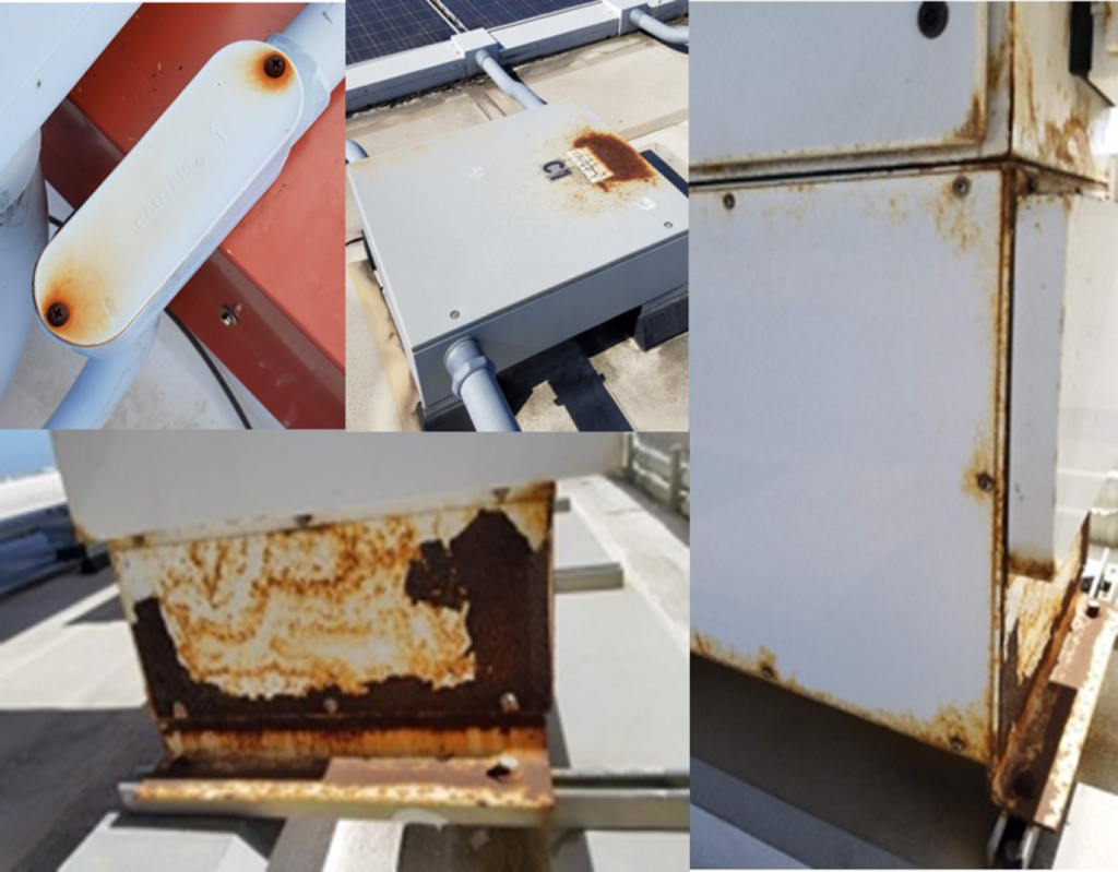
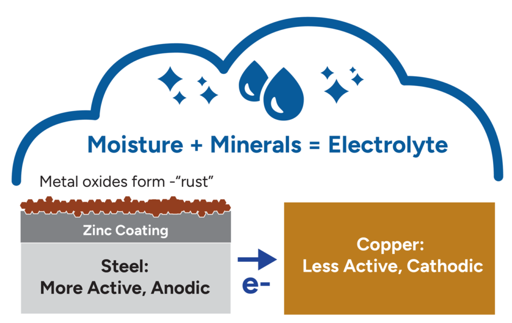
The three basic conditions
| Condition | What it means in a mounting system |
|---|---|
| Dissimilar conductive materials | For example, an aluminum rail and a stainless steel fastener |
| Electrical connection | Direct metal contact or another conductive path between the components |
| Common electrolyte | Rainwater, condensation or moisture containing dissolved salts or other contaminants |
If one of these essential conditions is absent, a galvanic corrosion cell cannot operate in the usual way.
However, a connection that appears dry during inspection may become wet during rain, condensation or periods of high humidity. Moisture trapped beneath washers, between overlapping surfaces or inside joints may also create intermittent exposure.
This is why material compatibility should be assessed for the service environment, not only for the condition of a new product in a warehouse.
2. Why Solar Mounting Systems Need Special Attention
A PV mounting structure is exposed to outdoor conditions for long periods. Its components may experience repeated wetting and drying, temperature changes, airborne contaminants and local moisture retention.
Typical material combinations include:
Aluminum rails connected with stainless steel bolts or T-bolts.
Aluminum clamps secured with stainless steel fasteners.
Stainless steel roof hooks connected to aluminum rails.
Aluminum brackets installed on galvanized or coated steel roofs.
Stainless steel screws passing through coated steel roof sheets.
Different metal components assembled with washers, gaskets or insulating interfaces.
These combinations are not automatically unacceptable. Their suitability depends on the actual design and exposure conditions.
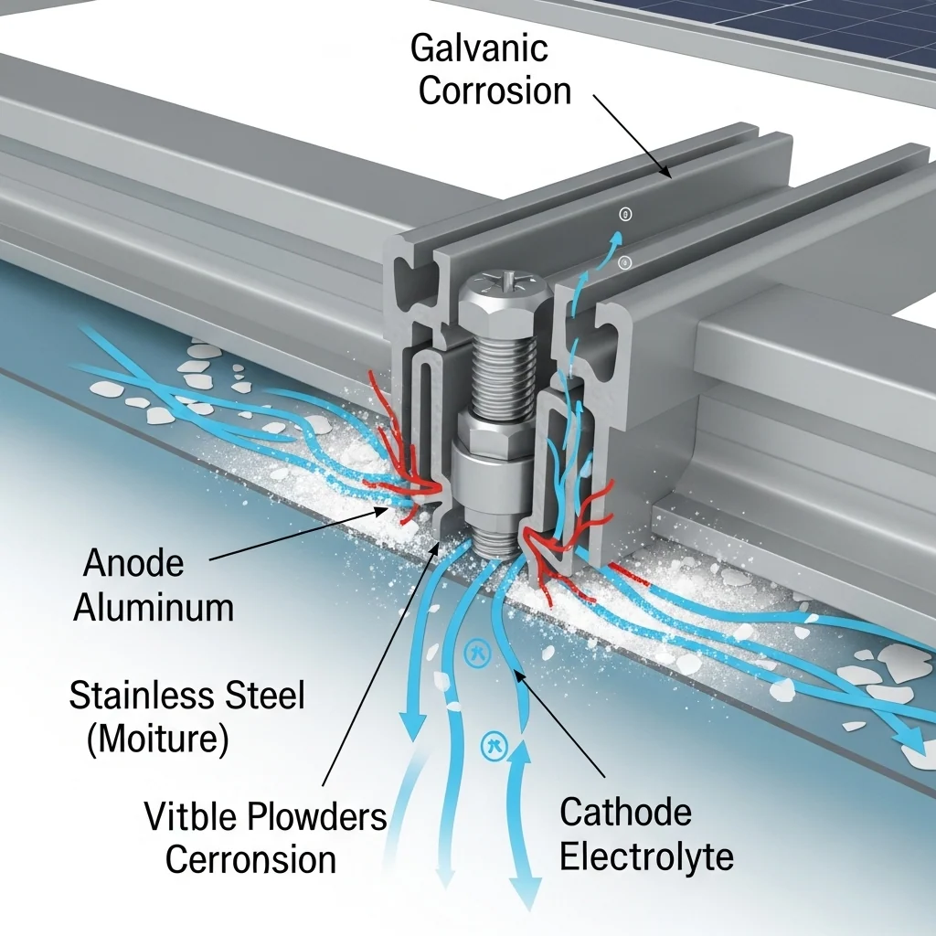
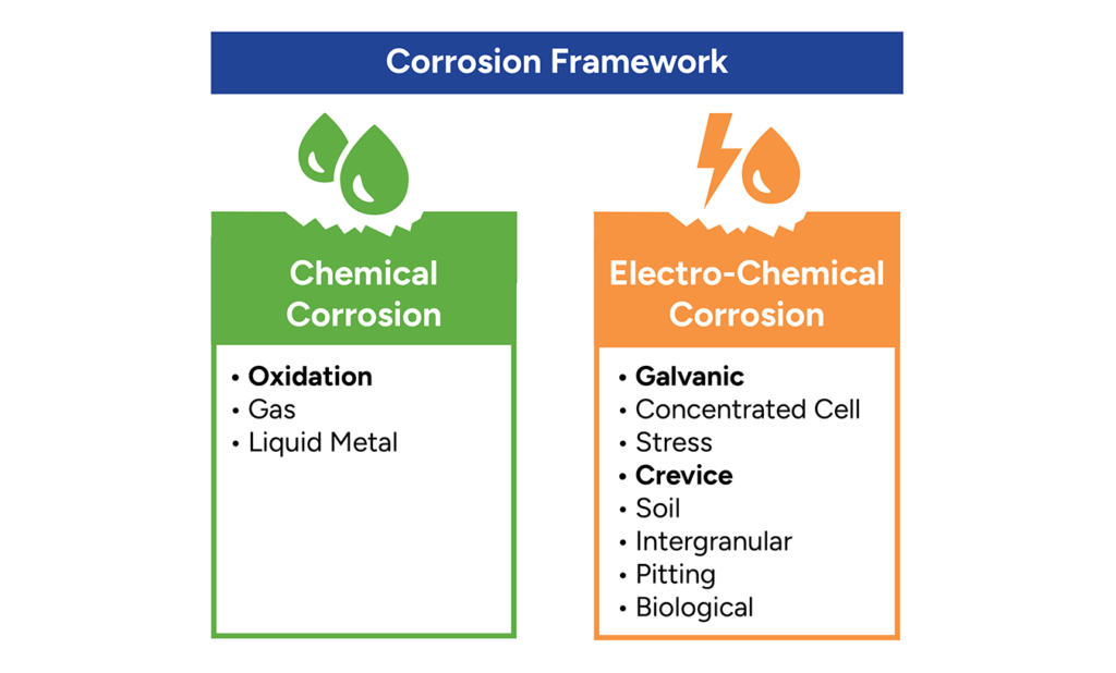
A mounting component may also be exposed to more than one corrosion mechanism. Galvanic corrosion should not be confused with general atmospheric corrosion, pitting corrosion, crevice corrosion or corrosion of a protective coating.
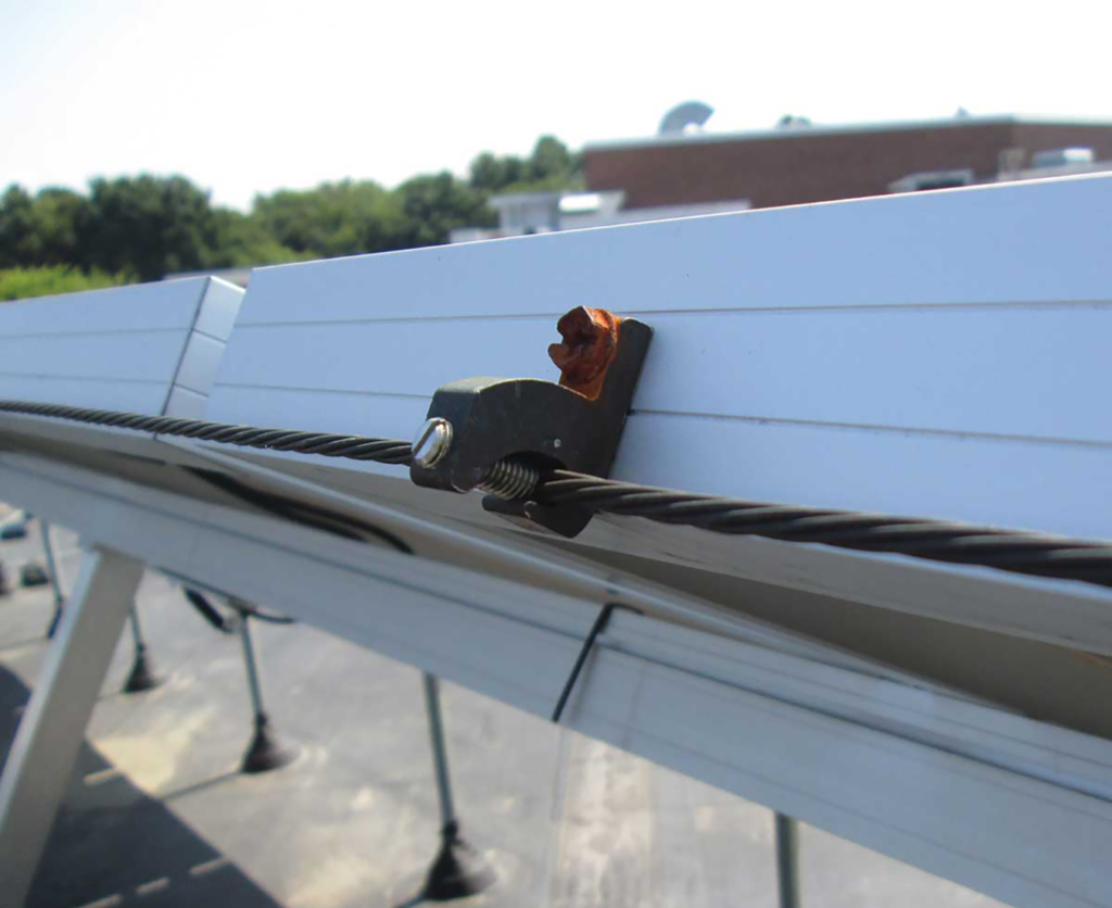
For example, corrosion around a stainless steel fastener in an aluminum component may involve galvanic effects, but retained moisture, chloride deposits, coating damage and crevice conditions may also contribute.
Identifying the actual mechanism matters because the appropriate corrective action may be different.
3. Five Factors That Influence Galvanic Corrosion Risk
3.1 Electrochemical potential difference
Metals and alloys have different electrochemical behaviors in a given environment.
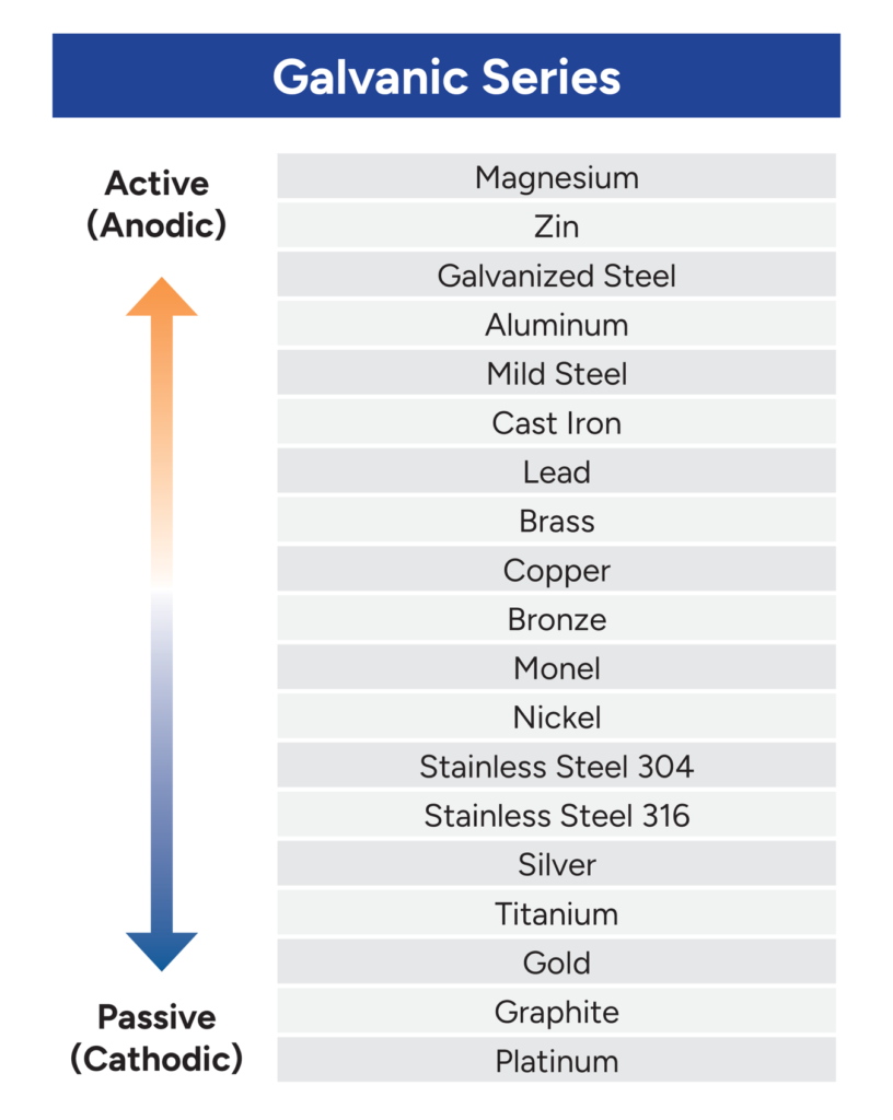
A galvanic series can help identify which material is likely to behave as the anode and which as the cathode.
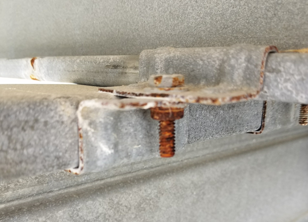
However, a galvanic series is not a universal compatibility table.
The relative position of materials can depend on the electrolyte and environmental conditions. Surface passivation and protective coatings can also affect actual behavior.
A table developed for seawater, for example, should not automatically be treated as a quantitative prediction for every rooftop environment.
For solar mounting applications, a galvanic series is best used as an initial screening tool. It does not replace assessment of the actual materials, connection geometry and exposure conditions.
3.2 Electrolyte conductivity
The electrolyte provides the ionic path needed to complete the electrochemical circuit.
Rainwater may provide some conductivity, while water containing dissolved salts or industrial contaminants can be more conductive.
Coastal environments deserve particular attention because airborne salt can deposit on mounting components and dissolve when moisture is present.
The same material combination may therefore behave differently in a relatively clean inland environment and in a salt-laden coastal environment.
The relevant question is not simply whether the project is near the sea. It is whether the connection is likely to experience conductive moisture, how often it becomes wet, and whether deposits remain on the surfaces.
3.3 Relative wetted surface area
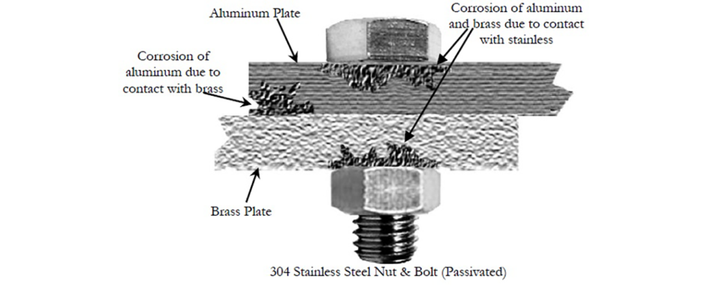
The area relationship between the anodic and cathodic materials is a major factor.
A particularly concerning arrangement is a relatively small anodic area connected to a much larger cathodic area, with both exposed to the same electrolyte.
The galvanic current can become concentrated on the smaller anodic area, increasing the local corrosion risk.
Consider two simplified examples:
Example A: Stainless steel fastener in a large aluminum component
A relatively small stainless steel fastener is connected to a much larger aluminum component. The wetted cathodic area may be limited compared with the exposed aluminum area.
This arrangement is commonly used in engineering applications, but local corrosion around the fastener can still occur under unfavorable conditions.
Example B: Small aluminum fastener connecting a large stainless steel component
A small anodic aluminum fastener is connected to a much larger cathodic stainless steel component.
This arrangement can create a more unfavorable area relationship, particularly where moisture and contaminants are present.
The examples illustrate why material names alone are insufficient. The actual wetted areas and geometry must be considered.
3.4 Surface condition and protective coatings
Aluminum, stainless steel and coated steel rely on surface characteristics that influence their corrosion behavior.
Examples include:
Anodized aluminum.
Painted or powder-coated aluminum.
Galvanized steel.
Zinc-aluminum coated steel.
Passivated stainless steel.
Organic coatings on roof sheets and mounting components.
A coating can reduce direct contact or limit environmental exposure when it remains intact and is suitable for the application.
However, coatings may be damaged during drilling, cutting, tightening, handling or installation. Fastener holes, edges, scratches and contact points deserve particular attention.
Anodizing should not be treated as a universal solution to galvanic corrosion. Its effectiveness depends on coating quality, continuity, damage, contact geometry and the actual electrical connection.
A coated component should therefore be assessed in its installed condition, not only by its original surface-treatment specification.
3.5 Connection geometry and moisture retention
The geometry of a connection can make a significant difference.
Potentially vulnerable locations include:
Overlapping metal surfaces.
Areas beneath bolt heads and washers.
Narrow gaps between brackets and rails.
Unsealed drilled holes.
Horizontal surfaces where water can collect.
Joints that retain dirt or salt deposits.
Damaged coating edges.
A joint that repeatedly retains moisture may experience a more aggressive local environment than an exposed surface that drains and dries quickly.
This is not exclusively a galvanic corrosion issue. Crevice conditions and localized corrosion may also develop.
Good drainage, accessible inspection points and suitable joint geometry are therefore important parts of corrosion control.
4. Common Material Combinations in Solar Mounting
The following table provides an initial screening perspective. It is not a universal approval matrix.
| Material combination | What should be checked |
|---|---|
| Aluminum rail + stainless steel fastener | Alloy, fastener grade, wetted area ratio, moisture retention and surface condition |
| Aluminum clamp + stainless steel bolt | Local contact area, coating condition, washer arrangement and exposure |
| Stainless steel roof hook + aluminum rail | Contact geometry, electrical connection, drainage and environmental exposure |
| Aluminum bracket + galvanized steel roof | Zinc coating condition, direct contact, water retention and coating damage |
| Stainless steel fastener + coated steel roof | Fastener penetration, exposed steel edges, coating compatibility and local moisture |
| Aluminum component + zinc-coated steel component | Actual coating system, electrical contact, electrolyte exposure and relative surface areas |
The table should not be used to approve or reject a combination without further information.
In particular, the presence of stainless steel does not automatically make a connection corrosion-proof. Similarly, the use of aluminum and stainless steel together does not automatically mean the assembly will fail.
5. How to Reduce Galvanic Corrosion Risk
Corrosion control should begin with the connection design, not with the assumption that a particular material grade will solve every problem.
5.1 Select compatible materials for the actual environment
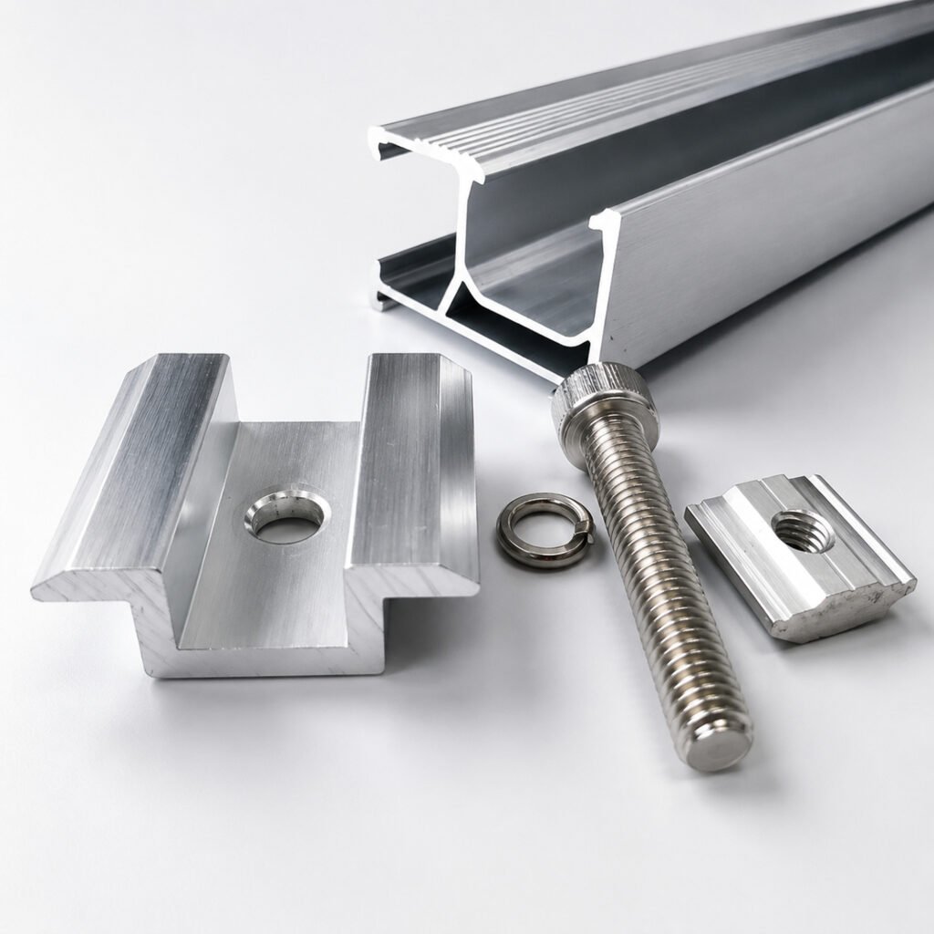
Material selection should consider:
Aluminum alloy and temper.
Stainless steel grade.
Steel coating type and thickness.
Surface treatment.
Environmental exposure.
Expected moisture and contaminant conditions.
Maintenance and replacement requirements.
A material designation alone does not establish the durability of the complete mounting assembly.
For demanding environments, the selection should be supported by relevant material compatibility guidance, manufacturer documentation or testing.
5.2 Use electrical isolation where appropriate
An insulating washer, sleeve, gasket or barrier may reduce electrical contact between dissimilar metals.
However, isolation must be designed as part of the complete connection.
Check:
Whether the insulating material separates the relevant conductive surfaces.
Whether bolt shanks or other hardware bypass the isolation.
Whether the material can withstand the installation pressure.
Whether it remains stable under outdoor exposure.
Whether water can enter and remain inside the joint.
Whether the isolation arrangement affects structural performance.
An insulating washer placed beneath a component does not necessarily isolate the entire connection if the fastener still creates another conductive path.
Isolation should also not be introduced without checking the mechanical and electrical requirements of the mounting system.
5.3 Prevent water retention and improve drainage
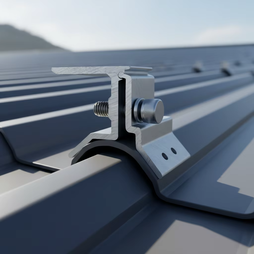
A connection that drains and dries effectively is generally easier to protect than one that retains moisture and contaminants.
Design considerations include:
Avoiding unnecessary water traps.
Providing suitable drainage paths.
Limiting gaps that retain contaminated water.
Avoiding geometry that collects debris.
Protecting exposed cut edges where required.
Maintaining the intended sealing arrangement.
For roof-mounted systems, corrosion control must not compromise the roof’s waterproofing details.
5.4 Protect surfaces during manufacturing and installation
Surface damage can expose less-protected material and create local corrosion sites.
Manufacturers and installers should consider:
Cutting and drilling methods.
Removal of burrs and sharp edges.
Protection of exposed cut surfaces where specified.
Handling and storage practices.
Avoiding damage to anodized or coated surfaces.
Using the specified fasteners and installation tools.
The appropriate repair or protection method should follow the coating or component manufacturer’s instructions.
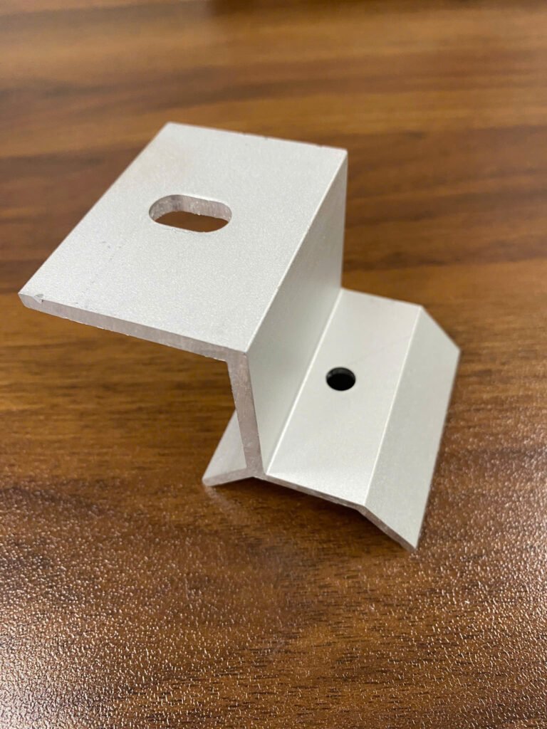
5.5 Verify the complete assembly
A material compatibility statement for one component pair does not prove the durability of the complete mounting system.
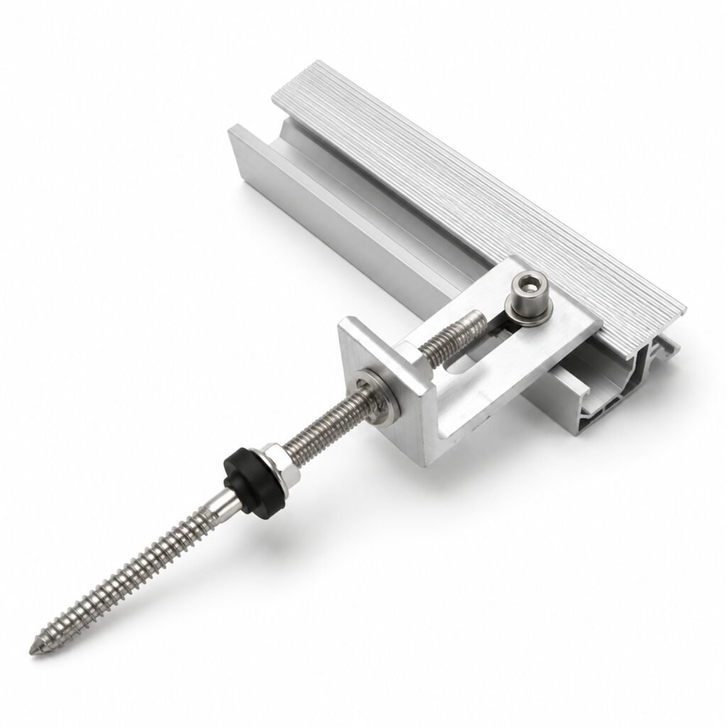
A meaningful assessment should identify the actual assembly, including:
Rail or mounting profile.
Bracket or clamp.
Fastener and washer.
Roof or supporting structure.
Surface treatment.
Contact arrangement.
Environmental exposure.
Where corrosion performance is critical, relevant testing should reproduce the important material combinations and exposure conditions as closely as practical.
6. Galvanic Corrosion Is Not the Only Corrosion Mechanism
A common mistake is to attribute every corrosion mark around a metal connection to galvanic corrosion.
Several mechanisms may occur in the same location.
| Corrosion mechanism | Typical concern in PV mounting |
|---|---|
| Galvanic corrosion | Dissimilar conductive materials connected through an electrolyte |
| General atmospheric corrosion | Exposure to moisture and environmental contaminants |
| Pitting corrosion | Localized attack, potentially associated with chloride exposure |
| Crevice corrosion | Moisture and aggressive chemistry retained in narrow gaps |
| Coating deterioration | Damage or degradation of protective surface layers |
| Under-deposit corrosion | Corrosion beneath accumulated dirt or salt deposits |
For example, visible corrosion around a bolt may be caused by damage to a protective coating, retained moisture, galvanic interaction or a combination of these factors.
A visual inspection alone may not establish the exact mechanism.
When corrosion damage is observed, the investigation should document the affected material, location, surface condition, moisture exposure, connection geometry and corrosion-product distribution before deciding on corrective action.
7. What Should Be Checked in a Solar Mounting Corrosion Assessment?
For an engineering review, the following information provides a useful starting point.
| Assessment area | Information required |
|---|---|
| Component materials | Alloy, grade, material specification and supplier |
| Surface treatment | Anodizing, passivation, galvanizing, coating type and relevant specification |
| Metal contact | Which components touch or have electrical continuity |
| Fasteners | Material, grade, coating, washer and sleeve arrangement |
| Connection geometry | Contact area, wetted area, joint gaps and exposed edges |
| Environment | Coastal, industrial, rural or other relevant exposure conditions |
| Moisture | Rain exposure, condensation, drainage and water retention |
| Protection | Insulating components, coatings, sealing and drainage details |
| Evidence | Manufacturer guidance, compatibility assessment and relevant test reports |
| Maintenance | Inspection access, replacement requirements and expected service conditions |
The assessment should be based on the actual configuration rather than a generic statement such as “stainless steel is suitable for outdoor use.”
8. What Should Buyers Ask a Solar Mounting Supplier?
For EPCs, distributors and mounting-system buyers, corrosion compatibility should be part of technical qualification.
The following questions 8. What Should Buyers Ask a Solar Mounting Supplier?
For EPCs, distributors and mounting-system buyers, corrosion compatibility should be part of technical qualification.
The following questions can help identify whether a supplier has evaluated the complete material combination.can help identify whether a supplier has evaluated the complete material combination.
Material identification
What aluminum alloy and temper are used for the rail, clamp or bracket?
What stainless steel grade is used for the fasteners?
Are the roof attachment and supporting components galvanized, coated or otherwise surface-treated?
Can the supplier provide material specifications or relevant documentation?
Connection design
Which components are in direct metal-to-metal contact?
Are insulating washers, sleeves or other barriers used?
Does the fastener create another electrical path that bypasses the insulating component?
Does the connection geometry retain water or contaminants?
Environmental suitability
Has the material combination been assessed for the intended project environment?
Is there specific guidance for coastal or industrial exposure?
Are exposed cut edges and installation damage addressed?
vidence and verification
Is the compatibility assessment based on manufacturer guidance, engineering evaluation or testing?
If corrosion testing has been conducted, does the test represent the actual materials, surface treatments and connection geometry?
What are the limitations of the available evidence?
A supplier should be able to explain the material selection and its limitations. A simple statement that a product uses “304 stainless steel” or “anodized aluminum” is not a complete corrosion assessment.
9. What Can a Corrosion Test Report Actually Prove?
Corrosion testing can provide useful evidence, but the test method and specimen configuration must match the intended claim.
A report should identify:
The test method and revision.
The tested materials and grades.
Surface treatments and coating specifications.
Specimen geometry and connection arrangement.
Whether dissimilar materials were electrically connected.
The exposure medium and test conditions.
Exposure duration.
Inspection and evaluation criteria.
Observed corrosion locations and severity.
Any deviations from the intended product configuration.
A salt-spray exposure result, for example, should not automatically be interpreted as a prediction of actual outdoor service life.
Likewise, a test on a standalone aluminum profile does not establish the corrosion performance of an assembled aluminum rail, stainless fastener, washer and coated roof interface.
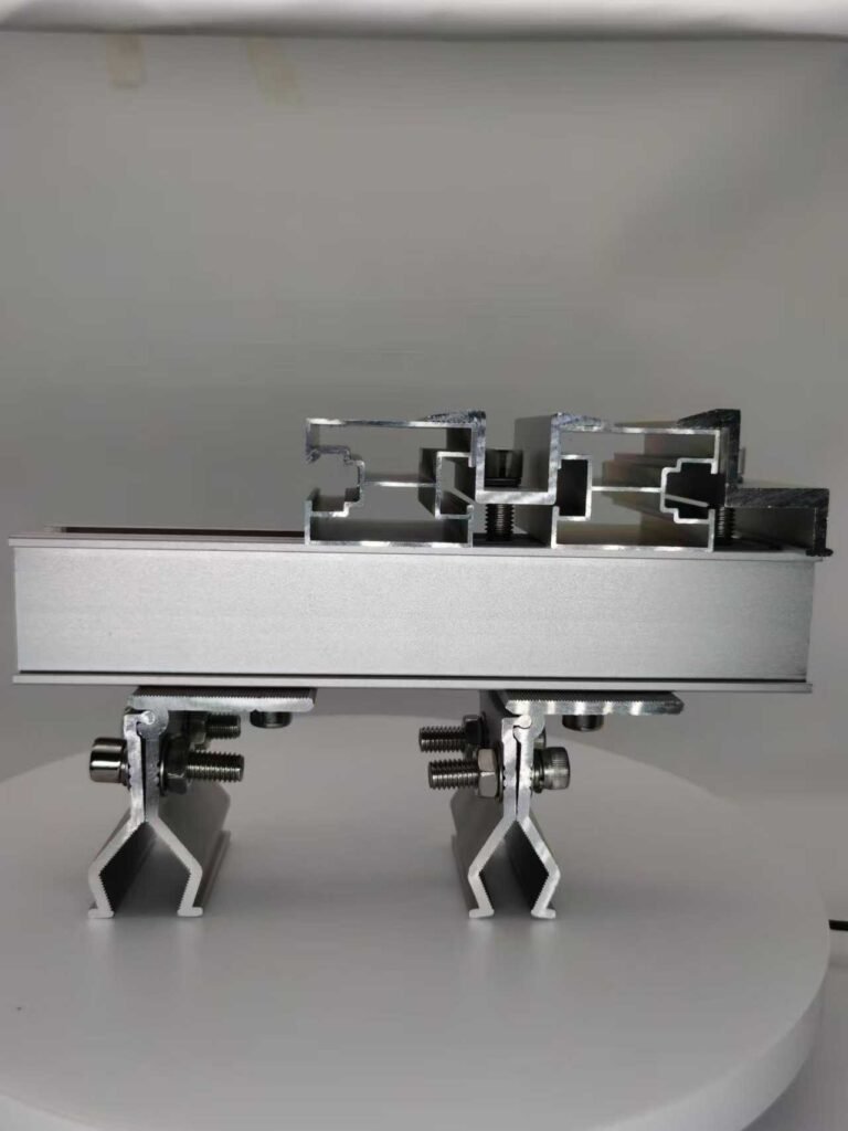
The test must represent the relevant corrosion mechanism and assembly if it is being used to support a system-level claim.
For additional technical context, ASTM G82 provides guidance on developing and using galvanic series, while ASTM G71 addresses conducting and evaluating galvanic corrosion tests in electrolytes. These documents serve different purposes and should not be treated as interchangeable product certifications.
10. A Practical Decision Framework
Before approving a material combination for a PV mounting system, follow this sequence.
Step 1 — Identify the materials
Confirm the actual alloys, grades, coatings and surface treatments. Do not rely only on broad descriptions such as aluminum or stainless steel.
Step 2 — Identify electrical connections
Determine whether the components are in direct contact or connected through another conductive path.
Step 3 — Identify the electrolyte exposure
Consider rain, condensation, salt deposits, industrial contaminants and moisture retained inside the joint.
Step 4 — Evaluate the area relationship
Consider the relative wetted anodic and cathodic areas, not only the overall dimensions of the components.
Step 5 — Review the connection geometry
Check drainage, crevices, coating damage, exposed edges and the possibility of moisture accumulation.
Step 6 — Select appropriate protection
Where necessary, use material changes, electrical isolation, protective coatings or improved drainage. Confirm that the measures do not compromise structural or electrical requirements.
Step 7 — Verify the evidence
Use manufacturer documentation, engineering assessment or testing that represents the actual connection and environment.
The final decision should be based on the complete mounting assembly and its intended service conditions.
Conclusion
Galvanic corrosion in solar mounting systems is not determined by material names alone.
Aluminum, stainless steel and coated steel can be used together in many engineered applications, but the actual risk depends on electrical contact, electrolyte exposure, electrochemical behavior, wetted surface area and connection design.
The most reliable approach is to assess the complete connection rather than approve or reject a material pair based on a simplified galvanic series.
For a solar mounting system, corrosion resistance is a system-level consideration involving material selection, surface treatment, fastener design, drainage, installation and environmental exposure.
A technically responsible supplier should be able to explain why a material combination is selected, what conditions it is intended for and what evidence supports that decision.
Further Technical References
ASTM G71 — Standard Guide for Conducting and Evaluating Galvanic Corrosion Tests in Electrolytes
British Stainless Steel Association — Bimetallic (Galvanic) Corrosion
FEMA — Technical Bulletin 8: Corrosion Protection of Metal Connectors in Coastal Areas
BlueScope — Corrosion Technical Bulletin 12: Dissimilar Metals
Reference note: These sources explain general galvanic corrosion mechanisms and design considerations. They do not certify any particular solar mounting product or material combination.