
How to Evaluate a Solar Mounting Test Report
A solar mounting supplier may provide a load test report showing that a clamp, bracket, rail or mounting assembly has passed a mechanical test. The report may include a maximum load, a failure load, a test standard or a laboratory name.
But what does that result actually prove?
A test report is only useful when the tested configuration, method, loading conditions and results are understood. A high load value from an isolated component test may have little relevance to a complete rooftop mounting system. A report from an accredited laboratory may still fall outside the laboratory’s accredited scope. A product tested to a recognized standard may also have limitations on the modules, roof profiles or installation configurations covered.
For EPCs, distributors, engineers and procurement teams, the key is not simply to ask whether a supplier has a test report. It is to determine whether the report provides evidence for the specific engineering question being asked.
This guide explains how to review a solar mounting test report, identify missing information and distinguish test results from product capacity, certification and project design approval.
1. Start With One Question: What Is the Report Supposed to Prove?
Before reviewing a report, define the claim it is being used to support.
A report may be intended to demonstrate:
The mechanical resistance of a clamp or bracket.
The pull-out resistance of a fastener in a defined substrate.
The load capacity of a rail connection.
The performance of a roof attachment under uplift.
The behavior of a complete mounting assembly.
The electrical bonding performance of a mounting connection.
The fire classification of a rooftop PV assembly.
The weather resistance of a roof penetration or mounting detail.
Compliance with a particular test method or certification requirement.
These are different questions. One test does not automatically answer all of them.
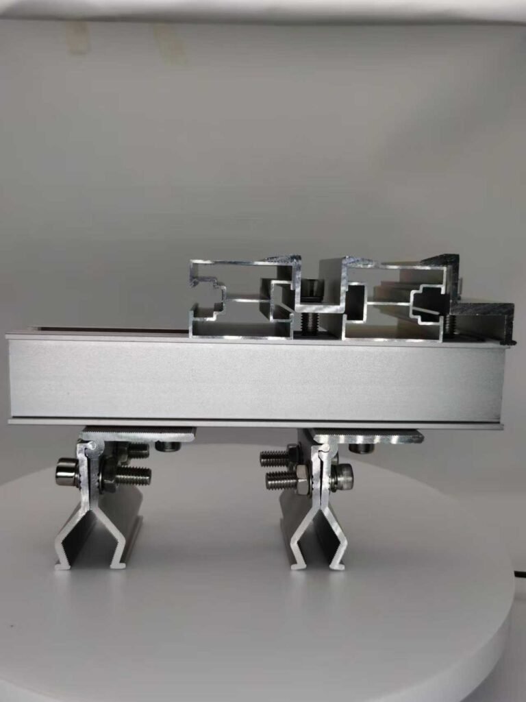
For example, a pull-out test on a hanger bolt installed in a timber specimen may provide evidence about that bolt-and-substrate configuration. It does not automatically establish the capacity of the complete system consisting of the bolt, L Foot, T-bolt, rail, clamps, modules and roof structure.
Similarly, a clamp load test does not automatically demonstrate electrical bonding performance.
The first rule is simple: identify the exact claim before interpreting the test result.
2. Understand the Difference Between a Test, a Calculation and a Certification
These forms of evidence serve different purposes.
| Evidence type | What it can establish | What it does not automatically establish |
|---|---|---|
| Component test | Observed behavior of a defined component and test setup | Complete mounting-system capacity |
| Assembly test | Observed behavior of the tested assembly | Performance of every possible installation configuration |
| Engineering calculation | Calculated resistance or structural adequacy under stated assumptions | Actual behavior outside the calculation model and its assumptions |
| Product certification / listing | Conformity within the defined certification scope | Unlisted products, combinations or performance attributes |
| Manufacturer specification | Manufacturer-defined product characteristics and application limits | Independent verification unless supported by appropriate evidence |
| Field performance records | Observed behavior in documented installations | Universal performance across different projects and environments |
A test report records what happened under defined test conditions. An engineering calculation uses a design method and stated assumptions to assess a structural condition. A certification or listing establishes conformity within a defined evaluation scheme and scope.
These documents may support one another, but they are not interchangeable.
Test result versus design resistance
A load-to-failure result is not automatically an allowable design value.
For example, a test may report that a bracket failed at a particular load. That result does not directly tell an engineer what load the bracket can safely resist in a project.
The engineering interpretation may need to consider:
The applicable design standard.
The required safety or resistance factors.
Test variability and sample quantity.
The observed failure mode.
Material and manufacturing variation.
Loading direction and boundary conditions.
Whether the tested configuration represents the intended installation.
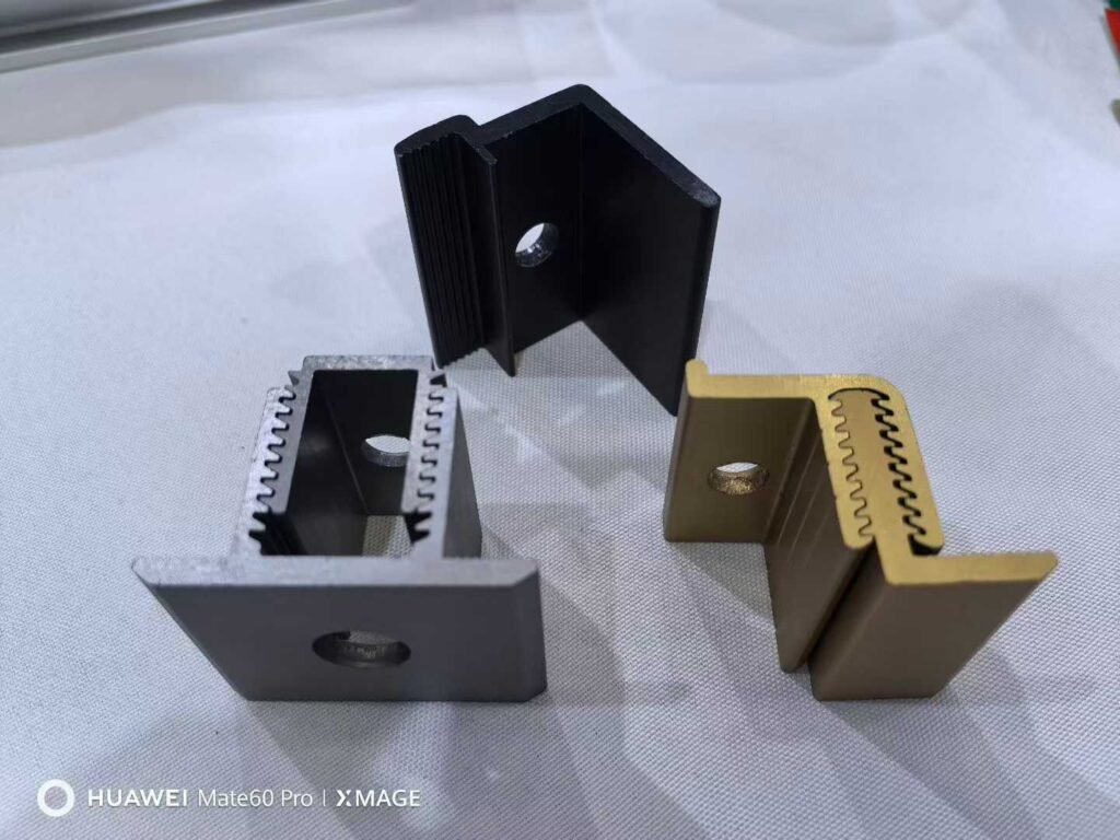
A reported maximum load should therefore not be copied directly into a project design calculation unless the applicable engineering method justifies that use.
3. Check the Laboratory and Its Accreditation Scope
The laboratory is an important part of the evidence chain, but its name alone is not enough.
3.1 Is the laboratory identifiable?
A credible report should allow the reader to identify the organization responsible for the test.
Check for:
Legal laboratory name.
Laboratory address or relevant testing location.
Report number.
Issue date.
Authorized approval or signatory information.
Contact or verification information where available.
If the report is issued by a third-party laboratory, verify the report through the laboratory when the project or procurement risk justifies it.
3.2 Does the laboratory hold ISO/IEC 17025 accreditation?
ISO/IEC 17025 establishes requirements for the competence, impartiality and consistent operation of testing and calibration laboratories. It is an important framework for evaluating laboratory competence. However, accreditation is linked to specific laboratory activities and an approved scope. https://www.iso.org/standard/66912.html
Do not stop after seeing an ISO/IEC 17025 logo.
Check:
Which accreditation body issued the accreditation?
Is the accreditation current?
Is the testing location covered?
Is the relevant test method included in the laboratory’s scope?
Does the scope cover the material, product category or measurement activity relevant to the test?
A laboratory may be accredited for some tests but not for every test it performs.
For this reason, the laboratory’s scope of accreditation should be reviewed alongside the report. https://www.iasonline.org/ias-testing-laboratory-accreditation-faqs/
3.3 Is an accredited report the same as an approved product?
No.
Laboratory accreditation concerns the laboratory’s competence to perform specified activities. It does not automatically certify the product being tested.
A test report from an accredited laboratory is evidence about the test performed. Product certification requires a separate conformity assessment process and a defined scope.
The distinction is particularly important when a supplier presents an accredited laboratory report as proof that a mounting component is “certified.”
The report should be evaluated for what it actually states, not for what the supplier’s marketing description implies.
4. Verify the Tested Product and Specimen
One of the most important parts of a mounting test report is the specimen description.
A report may contain a technically sound test result but still be unsuitable for a particular project if the tested product is different from the product being supplied.
4.1 Identify the exact component
Check whether the report identifies:
Product name and model.
Drawing or part number.
Material and grade.
Material thickness.
Dimensions and geometry.
Surface treatment or coating.
Fastener type and specification.
Washer, gasket or other interface materials.
Manufacturing or specimen identification where relevant.
For a customized mounting component, confirm whether the tested specimen matches the proposed production design.
A small change in thickness, hole position, bracket geometry, fastener arrangement or material may change the mechanical behavior.
4.2 Check the complete assembly
For a mounting-system test, the specimen description should identify the relevant connected components.
Depending on the product, this may include:
PV module and frame.
Rail.
T-bolt and nut.
Roof attachment or bracket.
Fasteners and washers.
Roof sheet or supporting substrate.
Supporting frame or test fixture.
A test on an isolated component should not be presented as evidence for a complete assembly unless the report and engineering evaluation establish the relationship.
4.3 Check whether the tested configuration matches the supplied configuration
Compare the report against the actual product drawing, BOM and installation instructions.
| Item | What to compare |
|---|---|
| Product model | Tested model versus quoted model |
| Geometry | Dimensions, thickness, holes, slots and contact surfaces |
| Material | Alloy, grade, temper or material specification |
| Surface treatment | Anodizing, galvanizing, coating or passivation |
| Fasteners | Type, size, grade, quantity and arrangement |
| Installation | Orientation, torque and assembly sequence |
| Interfaces | Module, rail, roof profile and substrate |
| Support conditions | Span, spacing, fixture and boundary conditions |
If the test specimen differs from the production product, the supplier should explain the differences and provide an engineering basis for applying the result.
Do not assume that a similar-looking product has the same test performance.
5. Review the Test Method and Standard
A report should identify the method used to conduct the test.
Check:
Standard number and title.
Edition or revision.
Any amendments.
Test procedure or laboratory method.
Deviations from the specified method.
Whether the test was conducted in full or only used selected parts of a method.
The standard should be relevant to the engineering question.
A standard may define how to test a roof assembly, a component, a material or an electrical function. These scopes are not interchangeable.
Examples relevant to solar mounting
ASTM E1592
This method addresses structural performance of sheet-metal roof and siding systems under uniform static air pressure. It is relevant when evaluating defined roof panel assemblies and their attachments, but it is not a universal capacity test for every solar mounting clamp.
UL 2703
UL 2703 covers PV mounting systems, mounting devices, clamping/retention devices and ground lugs for specified flat-plate PV modules and panels. The exact evaluation scope must be checked. https://shopulstandards.com/ProductDetail.aspx?UniqueKey=29007
Product-specific fastener or connection tests
A fastener pull-out test, bracket test or connection test may use a method developed for a particular product or application. The report should identify the method, fixture and conditions sufficiently for the reader to understand what was evaluated.
The important question is not whether a familiar standard number appears on the cover. It is whether the method is suitable for the claim being made.
6. Examine the Test Setup and Boundary Conditions
The test setup determines what the result represents.
A load value without the test configuration is incomplete information.
For solar mounting components, review the following details.
6.1 Specimen support and fixture
Check:
How the specimen was fixed.
Whether the support represents the intended installation.
Support spacing and dimensions.
Whether the fixture introduced additional restraint.
Whether the specimen could rotate, slip or deform as it would in service.
Whether the fixture was substantially stiffer than the actual supporting structure.
An overly rigid test fixture may produce a different result from a real roof or rail installation.
6.2 Loading direction
Solar mounting connections may experience different load directions.
Typical mechanical directions include:
Uplift or pull-out.
Downward pressure.
Shear parallel to the rail or roof slope.
Shear perpendicular to the rail or roof slope.
Combined loading.
Bending or eccentric loading.
A test in one direction does not automatically establish resistance in another.
For example, a standing-seam clamp tested in an uplift direction has not necessarily been qualified for drag loading parallel to the seam.
6.3 Loading method and rate
Check how the load was applied:
Static or cyclic.
Monotonic or repeated.
Load-controlled or displacement-controlled, where relevant.
Loading rate.
Number of loading cycles.
Hold periods.
Conditioning before testing.
These factors can influence the observed response and failure mode.
A single monotonic test should not be described as fatigue qualification.
6.4 Environmental and conditioning conditions
For tests involving corrosion, weather resistance, temperature or material durability, check:
Temperature and humidity.
Water or salt exposure.
Conditioning duration.
Pre-test treatment.
Number of cycles.
Inspection intervals.
Acceptance criteria.
A report should not be used to support environmental durability claims that were not part of the test.
7. Read the Results, Not Just the Maximum Load
A maximum load is only one part of a mechanical test.
A useful report should help the reader understand the behavior of the specimen throughout the test.
7.1 Load and displacement
Where applicable, check whether the report includes:
Load values.
Displacement measurements.
Load-displacement curves.
Maximum load.
Load at specified displacement.
Permanent deformation.
Residual movement after unloading.
Test termination criteria.
The load-displacement relationship may reveal behavior that a single maximum value cannot show.
For example, two brackets may reach similar maximum loads but exhibit very different deformation or stiffness.
7.2 Failure mode
The failure mode is essential to interpreting the result.
Potential failure modes in solar mounting systems include:
| Component or interface | Possible failure mode |
|---|---|
| Roof fastener( Tile Roof Hook) | Pull-out, shear failure or thread damage |
| Metal roof sheet | Pull-through, tearing or local deformation |
| Standing-seam clamp | Clamp slip, clamp deformation or seam failure |
| Rail | Bending, local buckling or excessive deformation |
| T-bolt connection | Bolt failure, rotation, disengagement or local rail damage |
| L Foot | Bending, deformation or connection failure |
| End clamp | Slip, deformation or fastener failure |
| PV module frame | Local deformation or damage |
| Frameless module interface | Glass damage or loss of retention |
The report should identify where failure occurred and, where possible, why it occurred.
A test may stop because a component fails, because a specified displacement is reached, or because the test setup reaches its limit.
These outcomes should not be treated as equivalent.
7.3 Did the test reach the intended failure condition?
If the report says “no failure” or “passed,” check the test termination criteria.
Possible explanations include:
The target load was reached without failure.
The test stopped at a predefined displacement.
The test stopped because the fixture reached its limit.
The specimen was removed after a specified number of cycles.
A non-structural issue prevented further testing.
A result should be interpreted against the actual acceptance criteria.
If the specimen did not fail, the report may establish that it sustained at least the applied test condition. It does not necessarily establish its ultimate capacity.
8. Check the Number of Specimens and Result Variability
A single test specimen can provide useful information, but it offers limited evidence about manufacturing variability.
For repeated tests, check:
Number of specimens.
Whether all specimens were identical.
Whether specimens came from different production batches.
Individual results.
Average and minimum values where reported.
Standard deviation or other variability information where applicable.
Whether any results were excluded and why.
Do not rely only on the highest result.
For engineering decisions, the lower-performing specimens and the consistency of the results may be more important than the maximum value.
The appropriate statistical treatment depends on the test method, product type and applicable design framework. Do not invent a statistical reduction factor when the report or design method does not provide one.
9. Understand the Difference Between Test Load and Design Capacity
This is one of the most important distinctions for mounting-system buyers.
Consider a simplified example:
A bracket is tested and the report records a maximum failure load of 5 kN.
Can the bracket be specified for a 5 kN design load?
Not automatically.
The engineer must determine whether the reported result is:
A maximum observed failure load.
A proof load.
A characteristic resistance.
An allowable resistance.
A design resistance.
A pass/fail threshold under a specific standard.
These terms have different meanings.
A design value may require a recognized calculation or evaluation method, statistical treatment, safety or resistance factors, and consideration of the applicable failure modes.
A test report should not be converted directly into a design value without that interpretation.
Questions to ask
Is the reported value a test load or a design resistance?
What failure criterion was used?
Was the test repeated?
How was variability considered?
Which design standard or evaluation method applies?
Are the relevant safety or resistance factors defined?
Does the result apply to the actual product and installation configuration?
If these questions cannot be answered, the reported maximum load should not be treated as an approved project capacity.
10. Check Certification and Listing Claims Separately
A test report and a product certification are different forms of evidence.
This distinction is particularly important when suppliers refer to UL 2703.
UL 2703 covers specific PV mounting systems, mounting devices, clamping/retention devices and ground lugs. However, the scope of an individual certification or listing must be checked. https://www.ul.com/services/pv-mounting-systems-certification
A mounting system may be evaluated for one or more attributes, such as:
Mechanical loading.
Grounding and bonding.
Fire classification.
These attributes should not be assumed to be included together.
UL’s guidance explains that the specific listing information identifies the evaluated features and the relevant modules, frames and mounting structures. https://code-authorities.ul.com/wp-content/uploads/sites/46/2022/09/Sept-Oct-2022-UL-Question-Corner_FINAL.pdf
When a supplier claims UL 2703 compliance, request the relevant certification or listing information and check:
Certification holder.
Product category and model.
Applicable modules and frames.
Rail and mounting configuration.
Evaluated attributes.
Installation requirements.
Allowable spans and cantilevers where applicable.
Any limitations or conditions.
Do not accept a generic UL 2703 statement as proof that every component or configuration is covered.
11. Check Whether the Report Applies to Your Project
Even a valid report may not apply to the proposed installation.
A project may use a different roof profile, sheet thickness, substrate, module frame, rail span or fastener arrangement.
The report should therefore be compared with the actual project conditions.
Product-specific applicability checklist
| Project variable | What must be compared |
|---|---|
| Roof profile | Exact profile or representative geometry |
| Roof material | Steel, aluminum or other material |
| Roof thickness | Tested thickness versus actual thickness |
| Substrate | Timber, steel purlin, concrete or other support |
| Fastener | Type, diameter, length, grade and quantity |
| Rail | Profile, span and orientation |
| Clamp | Model, dimensions and installation position |
| PV module | Manufacturer, model and frame geometry |
| Load direction | Tested direction versus project demand |
| Attachment spacing | Tested spacing versus proposed layout |
| Installation | Torque, orientation and assembly sequence |
| Environment | Relevant temperature, corrosion or weather conditions |
A report should not be generalized beyond its demonstrated scope without a justified engineering assessment.
For example:
A test on one trapezoidal roof profile does not automatically qualify every trapezoidal profile.
A pull-out test in one timber species or member size does not establish performance in every timber substrate.
A clamp tested with one module frame does not automatically qualify for a different frame geometry.
A rail test at one span does not establish the same resistance at a longer span.
The greater the difference between the tested and proposed configuration, the stronger the need for additional testing or engineering justification.
12. Common Warning Signs in Solar Mounting Test Reports
The following issues should trigger further questions.
| Warning sign | Why it matters |
|---|---|
| No clear product model or drawing | The tested specimen cannot be reliably matched to the supplied product |
| No material or thickness information | Mechanical behavior may differ from the actual product |
| No test setup drawing | Boundary conditions are difficult to evaluate |
| Only one maximum load is shown | Failure behavior and variability are unclear |
| No loading direction | The result cannot be applied confidently to the required load case |
| No failure mode | The governing weakness is unknown |
| No specimen count | Repeatability and variability cannot be assessed |
| Standard number shown without edition | The applicable test procedure may be unclear |
| Laboratory accreditation logo without scope | The relevant test may not be accredited |
| “Passed” without acceptance criteria | The basis for the conclusion is unclear |
| Different product shown in report and quotation | Product equivalence has not been demonstrated |
| Test value presented as allowable capacity | Test result and design resistance may have been confused |
| Certification logo without listing details | The actual certification scope remains unverified |
A missing item does not automatically mean the report is invalid. It means the reader should request clarification before relying on the report for an engineering or procurement decision.
13. A Practical Solar Mounting Test Report Review Checklist
The following checklist can be used by an EPC, distributor, engineering team or procurement department.
A. Report identity
Laboratory name and test location are identified.
Report number and issue date are available.
Product and specimen are identifiable.
Report approval or authorization is traceable.
Relevant attachments and appendices are included.
B. Laboratory competence
Laboratory accreditation status has been checked where relevant.
Accreditation body is identifiable.
Accreditation scope covers the relevant test activity if the report is claimed as accredited.
Testing location is covered.
Any subcontracted testing is disclosed where relevant.
C. Product and specimen
Product model and drawing are identified.
Material and thickness are specified.
Surface treatment is documented where relevant.
Fasteners and connection hardware are identified.
The specimen matches the proposed production configuration.
Any differences are explained.
D. Test method and setup
Test standard and edition are identified.
Deviations from the method are disclosed.
Test fixture and support conditions are documented.
Loading direction is clear.
Loading procedure and rate are available where relevant.
Environmental conditioning is documented where relevant.
E. Results and interpretation
Specimen count is stated.
Individual results are available where relevant.
Load and displacement data are provided where applicable.
Failure mode is identified.
Test termination criteria are explained.
Test values are distinguished from design resistance.
Statistical treatment and design factors are justified where used.
F. Project applicability
Roof profile and thickness are comparable.
Substrate and support conditions are comparable.
Fastener and rail configuration are comparable.
Module and clamp interfaces are comparable.
Load direction and spacing are relevant.
Installation instructions match the tested configuration.
Limitations are clearly understood.
G. Certification
Certification or listing is verified separately from the test report.
Evaluated attributes are identified.
Relevant module and mounting combinations are covered.
Installation conditions and restrictions are reviewed.
Review outcome: A report should be classified as applicable, conditionally applicable, insufficient for the intended claim, or requiring further testing/engineering review. Avoid reducing a complex report review to a simple “pass” or “fail” without stating the reason.
14. What Should You Request From a Solar Mounting Supplier?
A serious supplier should be able to provide more than a single-page load result.
For technical qualification, request:
Full test report, including relevant appendices.
Product drawing and part number.
Material and surface-treatment specification.
Fastener and hardware details.
Test specimen photographs or setup drawings.
Test method and edition.
Loading direction and boundary conditions.
Individual test results where available.
Failure mode and test termination criteria.
Laboratory accreditation details and relevant scope, where claimed.
Certification or listing information, if applicable.
Installation instructions and stated application limitations.
For a customized product, also request confirmation that the tested specimen corresponds to the proposed production design.
If the product has changed since testing, the supplier should explain whether the change affects the validity of the original evidence.
15. Example: How to Review a Roof Attachment Test Report
Imagine a supplier provides a report for a metal-roof solar bracket.
The report shows a maximum uplift result of 3.2 kN.
At first glance, the number may look useful. But before using it in a project, ask:
1. What was tested?
Was it the bracket alone, the bracket with screws, or the complete bracket-to-roof-sheet connection?
2. Which roof was used?
Was the test conducted on the same profile, material and thickness as the project roof?
3. How was the bracket installed?
Were the fastener type, number, position and installation procedure the same?
4. What was the support condition?
Was the roof sheet supported at the same spacing and by a comparable substrate?
5. What happened during the test?
Did the screws pull out, did the sheet pull through, did the bracket deform, or did another component fail?
6. What does 3.2 kN represent?
Is it a maximum failure load, a proof load or a design resistance calculated under a recognized method?
7. Does the result apply to the project?
If the actual roof profile, sheet thickness or fastener arrangement is different, additional evaluation may be required.
The number alone is not enough to approve the bracket.
The engineering value of the report comes from understanding the tested configuration, observed failure behavior and applicability to the intended installation.
Conclusion
A solar mounting test report should be evaluated as a complete technical document, not judged by its cover page, laboratory logo or highest load value.
A useful review establishes:
What product or assembly was tested.
Which method and test conditions were used.
Whether the laboratory was competent for the relevant activity.
How the specimen behaved and where it failed.
Whether the result represents a test load or a design value.
Which product configurations and project conditions the evidence can support.
What limitations remain.
For solar mounting systems, the most important question is always:
Does this report provide valid evidence for the exact component combination and installation condition being considered?
A professional supplier should be able to explain not only the test result, but also its scope, limitations and relationship to the proposed project.
That is the difference between presenting a test report and using engineering evidence responsibly.
Further Technical References
ISO/IEC 17025:2017 — General requirements for the competence of testing and calibration laboratories
UL 2703 — Mounting Systems, Mounting Devices, Clamping/Retention Devices, and Ground Lugs
Reference note: These sources explain laboratory competence and the scope of PV mounting certification. They do not validate any specific supplier’s test report or product.