
Solar Tile Roof Hook: Engineering Guide to Roof Compatibility, Rafter Attachment, Load and Tile Protection
A solar tile roof hook is not selected simply by matching the hook to the visible roof tile. The correct configuration depends on the tile profile, hook geometry, structural member, fastener, installation position, rail interface, project loads and weathering detail.
The key distinction is:
Tile compatibility ≠ structural capacity ≠ waterproofing performance ≠ installation approval.
For a defined project, the selection process should therefore follow:
Roof and tile identification → hook geometry → structural attachment → fastener qualification → tile protection → rail interface → project load verification → installation/weathering requirements
1. Why Tile Hook Selection Is More Than a Tile-Fit Question
Tile roofs vary considerably in profile, thickness, overlap, pitch and construction. A hook that physically fits one tiled roof cannot automatically be assumed suitable for another.
Important inputs include:
- tile type and profile
- tile dimensions and thickness
- tile overlap
- roof pitch
- batten and counter-batten arrangement
- rafter or other structural-member location
- available clearance beneath the tile
- hook geometry and adjustment range
- fastener type, diameter and length
- required structural embedment
- rail and T-bolt interface
- project wind and snow loads
- tile protection and weathering details
This is why “fits tile type X” is only the beginning of a technical qualification.
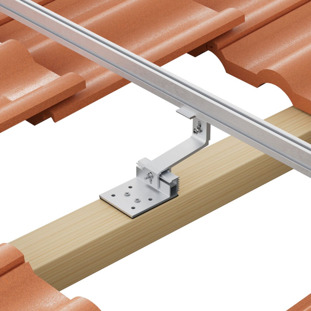
Manufacturer installation documentation illustrates this configuration-specific approach. For example, K2, Clenergy, IronRidge and Renusol provide different hook geometries and installation requirements for different tile-roof applications. These documents are useful evidence for their respective systems, but should not be treated as universal design approval for every tile hook or roof.
2. The Basic Load Path
A typical tile-roof PV attachment transfers structural loads through the hook and its fasteners into the supporting roof structure.
A simplified load path is:
PV module → module clamp → rail → tile hook → fastener → rafter/substrate → roof structure
The tile itself is normally not the component that should be assumed to carry the complete mounting-system structural load.
This distinction is important because several different failure modes can exist in the same connection:
- hook bending
- fastener withdrawal
- fastener shear
- inadequate embedment
- timber splitting
- insufficient edge distance
- substrate failure
- rail-to-hook connection failure
- local tile damage
The governing failure mode is determined by the complete connection, not by the hook alone.
A heavier or larger hook is therefore not automatically a proportionally stronger mounting connection.
3. What Determines Tile Hook Compatibility?
3.1 Tile Profile
The first question is not simply whether the roof is “tile.”
The actual tile profile matters.
Relevant characteristics include:
- profile shape
- tile thickness
- overlap
- troughs and valleys
- underside geometry
- available hook clearance
- batten position
- local bearing/contact area
Clay, concrete, plain, pantile and slate-type roofs may require different hook geometries or installation details.
A hook should not create an unacceptable point load on the tile or interfere with the tile’s intended position.
3.2 Tile Clearance
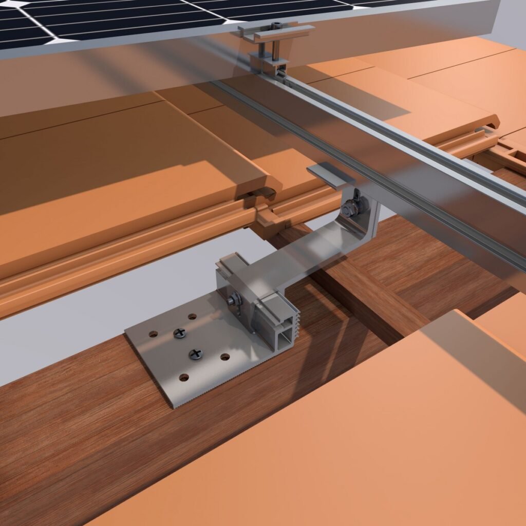
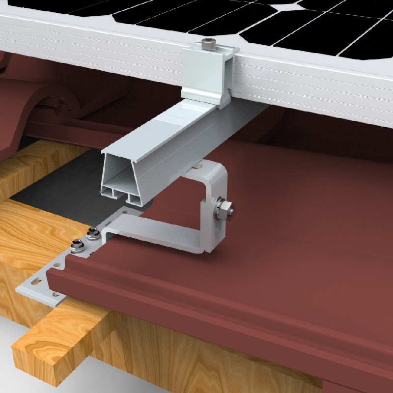
The hook must be positioned so that the tile can remain properly supported and the roof covering can accommodate the mounting component.
Insufficient clearance can result in:
- local tile loading
- cracking or breakage
- raised or displaced tiles
- interference with drainage
- installation difficulty
The required clearance is system-specific. It should be checked against the actual hook drawing and tile geometry rather than assumed from a generic hook dimension.
3.3 Rafter Position
The visible tile is not necessarily the structural attachment point.
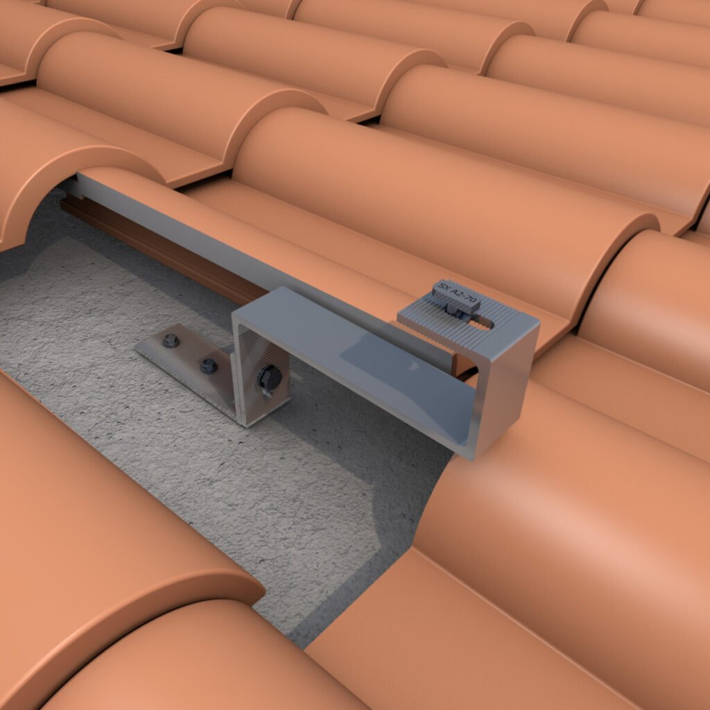
For conventional rafter hooks, the fasteners normally need to engage the designed structural member. The actual rafter position therefore becomes a critical selection input.
A difficult rafter location can affect:
- hook width
- adjustable reach
- fastener position
- edge distance
- installation access
- tile clearance
This is one reason adjustable or wider hook geometries exist in commercial mounting systems.
4. How Does the Hook Transfer Load Into the Rafter?
The hook itself is only one component in the structural connection.
The connection should be considered as:
Hook → fastener → structural member → building structure
The fastener connection depends on several variables:
- substrate material and properties
- rafter dimensions
- fastener type
- fastener diameter
- fastener length
- effective embedment
- edge distance
- pilot-hole requirements
- installation quality
- load direction
Total screw length is not the same as effective embedment.
A long screw does not automatically provide a high-capacity connection if part of its length passes through tile, battens, insulation or other non-structural layers.
For timber applications, the actual structural member, its dimensions and condition must therefore be identified before selecting the fastener.
The same principle applies to fastener diameter: increasing diameter does not by itself establish a fixed increase in connection capacity.
5. Fastener Selection and Installation
The correct fastener should be selected as part of the defined hook-and-substrate system.
Relevant questions include:
- What structural material is being fixed into?
- What are the member dimensions?
- What fastener type and diameter are specified?
- What effective embedment is required?
- Is a pilot hole required?
- What edge distance is available?
- What installation procedure applies?
- What loading directions need to be considered?
Installation manuals from established mounting-system manufacturers provide configuration-specific examples of fastener selection, pilot holes, edge distance and installation requirements.
For example, the K2 and Clenergy documentation in the evidence set provides installation requirements for their respective tile-hook systems. These are manufacturer-specific instructions and should not be converted into universal requirements for all hooks.
Torque is also system-specific. A torque value from one hook or fastener assembly should not be transferred to another product simply because the thread or nominal diameter appears similar.
6. Can a Tile Hook Damage the Roof Tile?
Yes. Tile damage is one of the important risks that must be considered during both selection and installation.
Potential mechanisms include:
- point loading from hook geometry
- insufficient clearance
- direct contact with a vulnerable part of the tile
- installation pressure
- incorrect tile positioning
- movement after installation
- notching that weakens the tile
- cracked or previously damaged tiles
The hook should therefore be positioned to provide adequate clearance and bearing conditions for the actual tile profile.
Where a tile needs to be notched or modified, the modification should preserve the tile’s integrity and the roof’s intended drainage path.
A visually acceptable installation is not necessarily an acceptable one if the hook introduces concentrated loading that can lead to cracking over time.
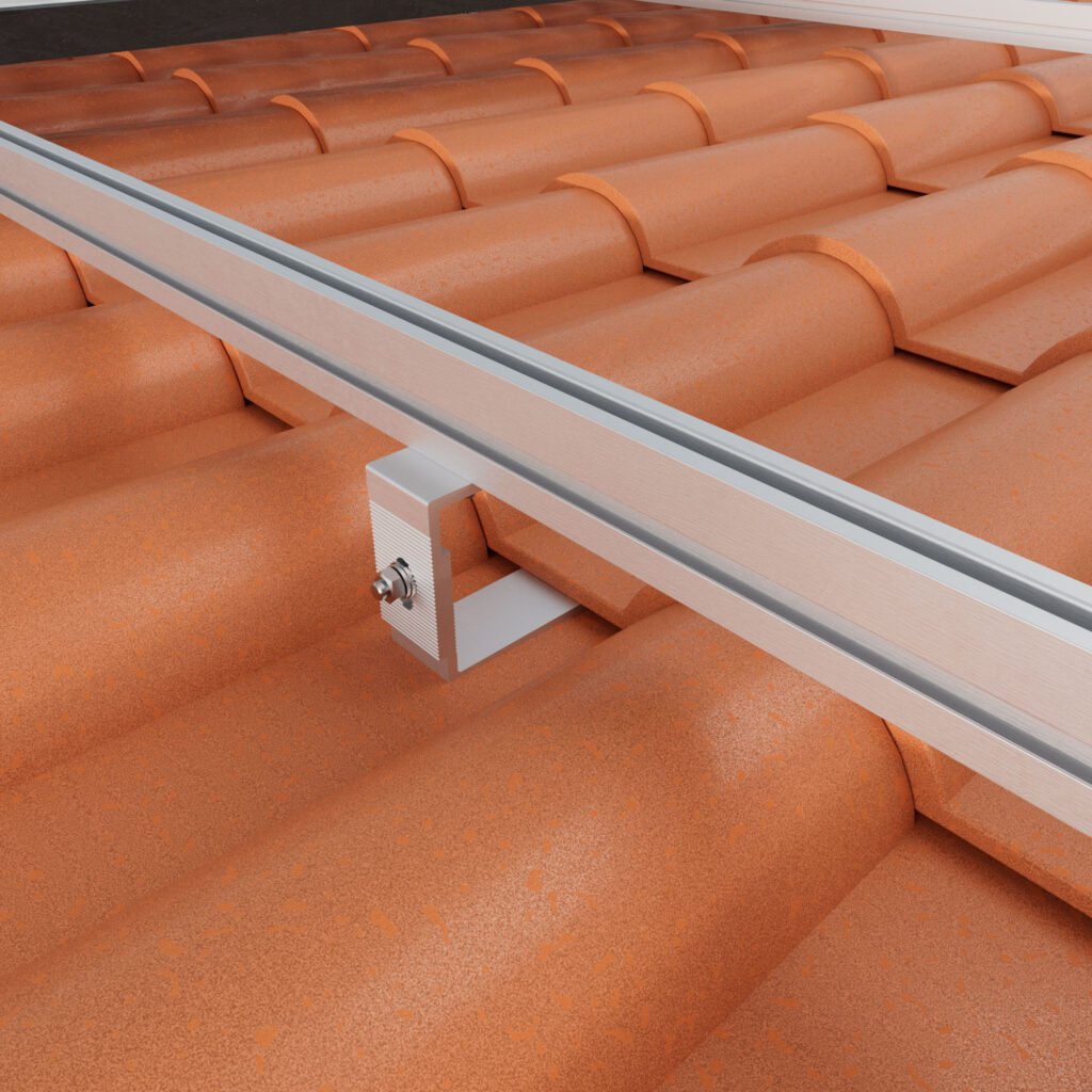
7. Tile Notching and Clearance
Some tile-hook systems require local modification of the tile to provide clearance around the hook.
This can involve:
- notching
- tile replacement
- local clearance adjustment
- protective or buffer components
The correct detail depends on the roof and mounting system.
The objective is not simply to make enough physical space for the hook. The installation must also avoid:
- unacceptable point loading
- tile displacement
- blocked drainage
- excessive stress concentration
- interference with adjacent tiles
This is why tile modification should be treated as an engineering and installation detail rather than an improvised site adjustment.
8. Waterproofing: A Separate Engineering Question
A tile hook can be structurally adequate while the roof detail is still poorly weathered.
The weathering chain should be considered separately:
Tile removal / notching → hook clearance → flashing / sealant / EPDM / butyl where specified → drainage path → weather resistance
The presence of a sealant or elastomer does not by itself prove long-term waterproofing performance.
Important variables include:
- roof pitch
- tile profile
- hook position
- flashing geometry
- sealing material
- compression
- drainage
- exposure
- installation quality
- aging and movement
The evidence registry includes manufacturer-specific sealing and weathering information such as K2 EverSeal testing. Such evidence should remain bounded to the tested or specified roof and sealing configuration.
A water test on one roof detail does not qualify every tile-hook installation.
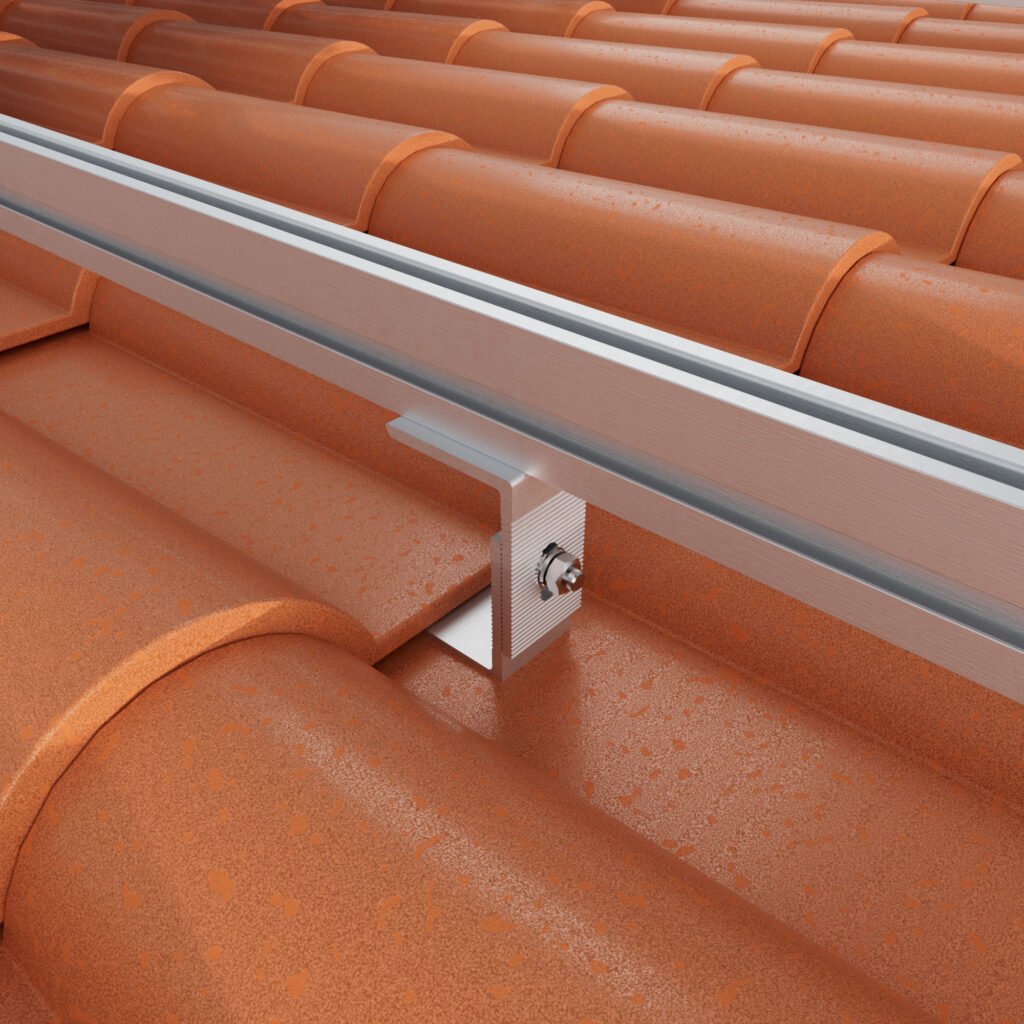
9. Does the Tile Carry the PV Load?
This is a common point of confusion.
For a conventional rafter-mounted tile hook, the intended structural load path normally leads through the hook and fastener into the structural member.
The tile is primarily part of the roof covering/weathering system rather than something that should automatically be treated as the structural support for the PV array.
This distinction matters because a hook may appear stable while the underlying structural attachment is inadequate.
The correct question is therefore not:
“Does the hook sit firmly on the tile?”
but:
“How does the complete attachment transfer the design loads into the building structure?”
10. How Much Load Can a Tile Hook Support?
There is no universal tile-hook capacity that can be applied independently of the mounting configuration.
Capacity depends on:
- hook geometry
- material and thickness
- fastener type and dimensions
- effective embedment
- rafter/substrate properties
- edge distance
- load direction
- hook installation position
- rail interface
- roof geometry
- project wind and snow loads
A manufacturer test value must also be distinguished from project design resistance.
A useful test report should identify, at minimum:
- hook model/configuration
- fastener
- substrate
- structural-member dimensions
- installation geometry
- load direction
- loading method
- failure mode
- test conditions
A numerical value without this configuration information is incomplete evidence.
Therefore, this article intentionally does not publish a universal kN capacity or universal hook spacing.
11. How Many Tile Hooks Are Required?
Hook quantity and spacing are project-dependent.
They should be determined from the complete load path and project design conditions, including:
- module arrangement
- rail span
- roof geometry
- wind load
- snow load where applicable
- roof zone
- hook capacity
- fastener/substrate resistance
- rail capacity
- attachment geometry
- building structure
The weakest relevant part of the load path can govern.
A hook manufacturer’s recommended spacing may be valid for a particular system and design condition, but it should not automatically be presented as a universal spacing rule.
12. Rail Interface Also Matters
The tile hook is not the end of the load path.
The hook must also interface correctly with the rail.
Relevant considerations include:
- rail cross-section
- hook geometry
- T-bolt or rail fastener
- engagement
- rail height
- adjustment range
- module-plane alignment
- eccentricity
Hook geometry can therefore affect not only roof attachment but also the final module position.
A hook that fits the tile but does not provide the required rail interface is not a qualified mounting solution.
13. A Practical Selection and Qualification Process
For a new tile-roof project, a useful sequence is:
Step 1 — Identify the roof
Collect:
- roof tile type
- manufacturer/profile where known
- tile dimensions
- tile thickness
- roof pitch
- tile overlap
- photos or drawings
Step 2 — Identify the supporting structure
Confirm:
- rafter location
- rafter dimensions
- timber grade/species or other substrate information where relevant
- batten/counter-batten arrangement
- insulation or other layers affecting fastener length
Step 3 — Select the hook geometry
Check:
- tile clearance
- hook width
- hook reach
- vertical adjustment
- contact/bearing condition
- rafter alignment
- rail interface
Step 4 — Qualify the fastener connection
Check:
- fastener type
- diameter
- length
- effective embedment
- pilot hole
- edge distance
- load direction
- substrate resistance
Step 5 — Check tile protection
Verify:
- clearance
- contact points
- point loading
- notching requirements
- tile condition
- drainage
Step 6 — Check weathering
Define:
- flashing
- sealing
- EPDM/butyl where applicable
- drainage
- tile reinstatement
- roof-specific weathering detail
Step 7 — Check the project design
Use the applicable structural design requirements for the project location and determine:
- wind actions
- snow actions where applicable
- roof zones
- design loads
- attachment spacing
- governing failure mode
For Australia and New Zealand projects, AS/NZS 1170.2:2021 is the relevant wind-actions standard referenced by Standards Australia for structural wind assessment. Standards Australia notes that the standard addresses wind effects on structures and is referenced by the Australian National Construction Code and the New Zealand Building Code.
For PV installation and safety requirements in Australia, the current AS/NZS 5033:2021 is listed by Standards Australia as the current edition. Its scope covers general installation and safety requirements for PV arrays.
For international PV array design, the current consolidated IEC 62548-1:2023+AMD1:2025 includes revised provisions relating to PV array design and mounting structures.
These standards do not turn a generic tile hook into a certified structural connection. They provide part of the applicable project/design framework; the actual roof attachment still requires configuration-specific engineering verification.
14. What Engineering Evidence Should Be Requested?
For supplier qualification or project approval, useful documentation can include:
Product information
- hook drawing
- dimensions
- material and finish
- rail interface
- adjustment range
- compatible roof/tile profiles
Installation information
- approved fasteners
- fastener dimensions
- pilot-hole requirements
- edge-distance requirements
- installation orientation
- torque where specified
- tile clearance/notching detail
Structural evidence
Where available:
- hook load testing
- hook-and-fastener testing
- substrate testing
- withdrawal/shear testing
- combined connection testing
- project-specific engineering calculations
Weathering evidence
Where relevant:
- flashing detail
- sealing detail
- weathering test
- installation procedure
- drainage detail
The evidence must always be checked for its exact scope.
A test on one hook, fastener and timber configuration does not automatically establish capacity for a different hook geometry, fastener, rafter or installation condition.
15. Standards and Authority: What They Do and Do Not Prove
Standards and certification references can strengthen engineering documentation, but they should not be used to imply a qualification that does not exist.
For example, UL 2703 covers PV mounting systems, mounting devices, clamping/retention devices and ground lugs. UL Solutions also explains that certification/listing parameters need to be checked for the specific intended use rather than assuming that a general “UL 2703” statement covers every configuration.
Likewise, IEC or AS/NZS PV installation standards provide requirements within their defined scope. They do not independently establish the structural capacity of an arbitrary tile hook.
The correct hierarchy is: Applicable standard/code → defined mounting configuration → evidence → project-specific design
not: Standard mentioned → product automatically approved
16. Common Tile Hook Selection Mistakes
Mistake 1 — Selecting only by tile name
Two roofs described as “concrete tile” can have materially different profiles and installation constraints.
Mistake 2 — Treating physical fit as qualification
A hook that fits beneath the tile may still have inadequate structural attachment, clearance or weathering performance.
Mistake 3 — Assuming the tile carries the load
The structural load path must be traced into the rafter or other designed supporting structure.
Mistake 4 — Selecting screws by length alone
Nominal screw length is not the same as effective structural embedment.
Mistake 5 — Using a universal hook spacing
Spacing depends on project loads, rail configuration, hook capacity, fastener/substrate resistance and roof geometry.
Mistake 6 — Ignoring tile damage
Point loading, inadequate clearance and poor notching can create durability problems even when the hook appears structurally stable.
Mistake 7 — Treating EPDM or sealant as a complete waterproofing design
Weather resistance depends on the complete roof detail, including drainage and installation.
Mistake 8 — Transferring another manufacturer’s test result
A test result applies to the tested configuration and defined scope. It should not be transferred to another hook or roof without engineering justification.
17. What Information Should Be Included in a Tile Hook RFQ?
A technically useful RFQ should include enough information to qualify the attachment rather than simply request a unit price.
Roof
- tile manufacturer/profile if known
- tile type
- tile dimensions
- tile thickness
- roof pitch
- roof photos
- roof drawings where available
- batten/counter-batten arrangement
Structure
- rafter dimensions
- structural-member spacing
- timber grade/species or substrate specification where relevant
- accessible fixing position
- insulation thickness or other layers affecting fastener length
Mounting system
- rail manufacturer/model
- rail cross-section
- T-bolt/rail interface
- module dimensions
- module layout
Engineering
- project location
- design wind requirements
- snow load where applicable
- roof zone
- design code
- required documentation
Procurement
- quantity
- target market
- material/finish
- sample requirement
- CAD requirement
- testing/documentation requirement
- OEM/ODM requirements
This information allows the supplier to move from “Which hook do you sell?” to the more useful question:
“Which hook, fastener and installation configuration is appropriate for this roof and project?”
18. Product and Engineering Boundary
A tile hook is a roof-attachment component within a larger PV mounting system.
Its suitability cannot be established independently of:
tile → hook → fastener → rafter/substrate → rail → module → project loads
The weathering system must also be assessed separately:
tile → hook clearance/notching → flashing/sealing → drainage → weather resistance
For this reason:
- hook capacity is not system capacity
- hook fit is not engineering approval
- fastener strength is not connection capacity
- a test value is not automatically project design resistance
- a sealing component is not automatically a complete waterproofing system
- a manufacturer installation guide is not universal approval for another system
The strongest qualification approach is:
Compatibility → Qualification → Project Design
For a defined roof, the required evidence can then be matched to the actual tile profile, structural member, fastener and project loading.
19. Conclusion
A solar tile roof hook should be selected as part of a defined roof-attachment system, not as an isolated hardware component.
The critical questions are:
- Does the hook fit the actual tile geometry?
- Can it reach and attach correctly to the structural member?
- Is the fastener connection adequately defined?
- Can the tile be protected from unacceptable local loading?
- Does the hook interface correctly with the rail?
- Is the weathering detail appropriate?
- Has the complete attachment been checked against project loads?
If these questions cannot yet be answered, the correct next step is not to guess a hook size or publish a universal capacity. It is to obtain the roof, tile, substrate and project information needed for qualification.
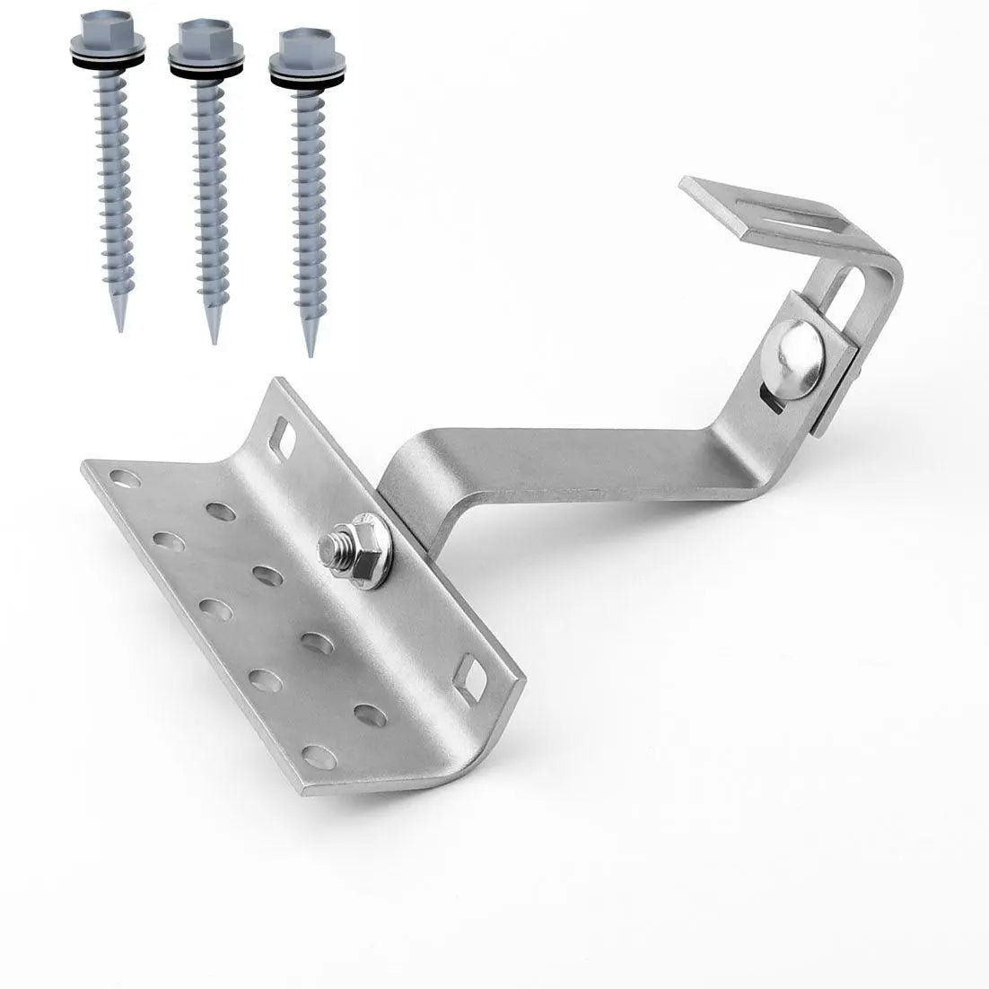
Have a specific tile roof?
Send us the tile profile or roof photos, rafter dimensions, rail information and project loading. We can review the hook, fastener and attachment configuration before quotation or sample development.