
Solar Panel Mid Clamp: Engineering Guide to Module Compatibility, Gap, Load and Installation
A solar panel mid clamp sits between two adjacent framed PV modules and secures both module frames to the mounting rail. Although the component is small, its performance depends on several interfaces working together: the two module frames, the required module gap, the clamp geometry, the rail, the T-bolt or rail fastener, and the supporting structure.
The important question is therefore not simply whether a mid clamp “fits” a module.
A proper evaluation should separate four questions:
- Does the clamp physically fit the module frames?
- Does it create the correct module-to-module gap?
- Is the module/clamp/rail configuration structurally qualified?
- Is the complete mounting system suitable for the project loads?
These are related questions, but they are not the same question.
1. What Does a Solar Panel Mid Clamp Do?
A mid clamp is installed between two adjacent framed PV modules.
Unlike an end clamp, which normally retains the outside edge of a module row, a mid clamp engages the edges of two neighboring modules simultaneously.
The typical load path is:
PV module frame → mid clamp → mounting rail → rail attachment → roof or ground structure
This means the mid clamp is only one part of the structural load path.
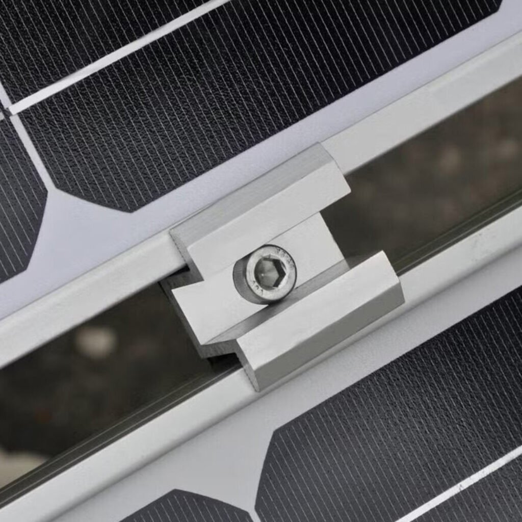
A mid clamp with adequate mechanical strength cannot compensate for an inadequate rail, weak rail connection, unsuitable module frame, or insufficient roof attachment.
The key interfaces are:
- first module frame
- second module frame
- module-to-module gap
- clamp body and contact surfaces
- T-bolt or other rail fastener
- rail channel
- rail span and orientation
- rail-to-structure attachment
- module manufacturer’s approved clamping zone
For this reason, mid-clamp selection is best treated as an interface and system-qualification problem, rather than simply a hardware selection problem.
2. Will a Mid Clamp Fit My Solar Module?
Not necessarily.
The most obvious specification is module frame height, but frame height alone is not enough to establish compatibility.
A proper compatibility check should consider at least:
- frame height
- frame thickness
- return-flange geometry
- clamp engagement
- contact area
- approved clamping zone
- required module gap
- clamp geometry
- rail interface
- T-bolt or fastener geometry
Two modules may both be described as having the same nominal frame height while having different frame cross-sections.
Likewise, two mid clamps may both be advertised for the same nominal frame height but have different contact geometry or rail interfaces.
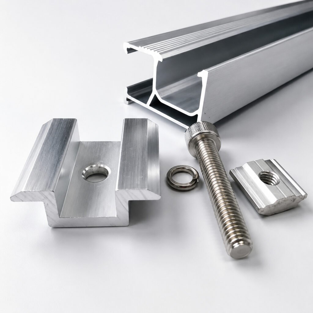
Therefore:
A stated frame-height range should be treated as a selection parameter, not as universal proof of compatibility.
The module manufacturer’s installation documentation should be checked before final approval.
The manufacturer’s specified mounting or clamping zone is particularly important because the mechanical-load capability of a PV module is tied to defined support and mounting configurations.
3. Why Module Frame Geometry Matters
The mid clamp transfers force into the module frames at their edges.
The quality of this interface depends on how the clamp contacts the frame.
Important variables include:
Frame height
The clamp must be designed for the actual frame height.
A clamp intended for one frame-height range should not automatically be assumed suitable for another range simply because the dimensions appear close.
Frame thickness and flange geometry
The vertical height of the frame does not describe the entire cross-section.
The clamp may interact with the frame’s flange, return section, or other geometry. A difference in these features can affect engagement and contact.
Clamp overlap or grip
The clamp needs sufficient engagement with both intended module frames.
Insufficient engagement can reduce retention performance and may change the effective load path.
Approved clamping zone
The module manufacturer may specify where clamps or supports can be positioned.
The fact that a clamp physically reaches the frame does not mean that the module is qualified for that installation position.
Module gap
The two modules must be positioned so that the mid clamp can engage both frames correctly while maintaining the required spacing.
This makes the gap part of the mechanical interface rather than merely an aesthetic spacing dimension.
4. What Module Gap Should a Mid Clamp Create?
There is no single universal module gap that applies to every mounting system.
The correct gap depends on the particular:
- mid-clamp geometry
- module frame geometry
- rail system
- installation method
- module manufacturer’s requirements
- mounting-system instructions
A common mistake is to select a clamp based on frame height and then assume that the resulting module spacing will automatically be correct.
That reverses the engineering sequence.
The correct sequence is:
Module → mounting requirements → clamp geometry → rail system → installation method
The installer should verify that:
- both module frames are properly engaged;
- the clamp is positioned as specified;
- the intended module gap is achieved;
- the clamp does not interfere with the module frame;
- the rail and fastener are correctly aligned.
The gap should therefore be treated as a controlled installation dimension, not simply as the empty space between two modules.
5. Does the Rail Affect Mid-Clamp Performance?
Yes.
The mid clamp does not carry the complete load independently.
The load continues from the clamp into the rail through the T-bolt, rail fastener, or other specified interface.
The simplified load path is:
Module A frame
↓
Mid clamp
↓
T-bolt / rail fastener
↓
Rail
↓
Rail attachment
↓
Roof / ground structure
and simultaneously:
Module B frame
↓
Mid clamp
Both module frames therefore participate in the connection.
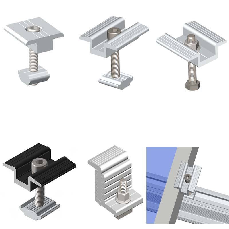
This creates an important engineering boundary:
Mid-clamp performance cannot be separated completely from the rail and its fastening interface.
A clamp that is mechanically adequate in one rail system cannot automatically be transferred to another rail system.
The rail channel dimensions, T-bolt geometry, fastener engagement and installation orientation can all affect whether the connection is correctly assembled.
6. How Much Load Can a Solar Panel Mid Clamp Hold?
There is no universal mid-clamp capacity that applies independently of the module, rail, fastener and installation configuration.
A published capacity value, where available, must be understood in the context of the configuration under which it was established.
The governing limit could occur at different points in the load path:
- module frame
- clamp
- T-bolt or rail fastener
- rail
- rail connection
- roof attachment
- supporting structure
For example, a stronger clamp does not automatically produce a stronger PV mounting system if the rail connection or supporting structure governs.
This is why the question:
“How many kilograms can one mid clamp hold?”
is usually incomplete for engineering purposes.
A more useful question is:
“For this module, clamp, rail and attachment configuration, under the defined project loading, what component or connection governs the design?”
That is the question that leads to an engineering qualification.
7. Why the Two Module Frames Matter
An end clamp normally interacts with one module frame.
A mid clamp interacts with two adjacent module frames.
This creates an additional interface condition.
Both sides of the clamp need to engage the intended frame geometry correctly.
If one module is positioned differently from the other, or if one frame has different geometry, the nominal clamp specification may no longer describe the actual connection.
This is particularly relevant when:
- different module models are mixed in one project;
- modules from different generations have different frame designs;
- modules have similar dimensions but different frame sections;
- replacement modules are introduced later;
- a clamp is being reused for a new module family.
A mid clamp that works correctly with one module pair should not automatically be assumed to work with another pair.
8. Can One Mid Clamp Fit Different Module Frame Heights?
Sometimes, but the stated frame-height range is not enough to establish universal compatibility.
For example, some commercial mid-clamp systems are designed for a defined range of module frame heights. That range can be useful for preliminary selection.
However, the actual qualification still depends on the complete interface.
The following should be checked:
| Check | Why it matters |
|---|---|
| Frame height | Determines basic clamp geometry |
| Frame thickness | Affects physical engagement |
| Frame profile | Determines contact and interference |
| Approved clamping zone | Determines whether the module accepts the support position |
| Clamp overlap/grip | Affects the module-to-clamp interface |
| Module gap | Determines whether both frames are correctly engaged |
| Rail interface | Determines whether the clamp can be correctly secured |
| Fastener/T-bolt | Affects connection and installation |
| Project loading | Determines structural qualification |
Therefore, “fits 30–40 mm frames” should not be interpreted as:
“Fits every PV module with a 30–40 mm frame.”
The latter is a much stronger claim and requires evidence that covers the relevant module-frame geometries and system configuration.
9. Can a Mid Clamp Cause Module Damage?
Incorrect installation can create risk at the module-frame interface.
Potential problems include:
- insufficient frame engagement;
- incorrect clamp position;
- interference between clamp and frame;
- excessive installation force;
- incorrect module gap;
- incorrect torque;
- use outside the module manufacturer’s approved mounting zone.
The exact failure mechanism depends on the module frame and clamp design.
This is another reason why installation instructions should not be replaced by a generic statement such as “tighten firmly.”
The objective is not simply to maximize clamping force.
The objective is to achieve the specified interface, engagement and installation condition.
10. What Torque Should Be Used?
There is no universal torque value for all solar mid clamps.
Torque is product- and system-specific.
Installation documentation may specify a particular torque based on the clamp, fastener, rail and intended mounting system.
For example, manufacturer documentation for established mounting systems can specify:
- T-bolt orientation;
- clamp positioning;
- module placement;
- required engagement;
- torque;
- hardware reuse or single-use requirements.
These instructions should be followed for the actual mounting system.
Increasing torque is not a general method of increasing wind resistance.
Excessive tightening can create installation problems, including misalignment or other unintended effects depending on the system design.
For an OEM or custom mid clamp, the torque requirement should therefore be established together with the hardware and rail interface rather than selected independently.
11. Does the T-Bolt or Rail Fastener Affect Capacity?
Yes.
The mid clamp, fastener and rail form one connection.
A technically suitable clamp body can still be unsuitable if the fastener or rail interface does not provide the required engagement or installation condition.
Important questions include:
- Is the T-bolt compatible with the rail channel?
- Is the fastener correctly oriented?
- Is sufficient engagement achieved?
- Is the specified hardware being used?
- Is the clamp positioned correctly?
- Is the rail itself suitable for the design loading?
- Does the installation method match the manufacturer’s instructions?
The connection should therefore be evaluated as an assembly.
12. Does a Mid Clamp Provide Grounding or Bonding?
Some mid-clamp systems are designed to provide electrical bonding or grounding functionality.
However, this should not be assumed for every mid clamp.
Mechanical clamping and electrical bonding are related but distinct functions.
Where a mid clamp is intended to provide bonding, the applicable certification or listing should be checked for the specific:
- clamp;
- module frame;
- rail or mounting structure;
- installation configuration.
UL 2703 is relevant to PV mounting systems, including clamping/retention devices and grounding-related functions. However, a statement such as “UL 2703 compliant” does not by itself establish universal mechanical capacity or universal compatibility.
The specific listing scope and installation conditions need to be verified.
Similarly, IEC 61215 is a PV module qualification framework. A module qualified under IEC 61215 is not thereby automatically qualified for every third-party mid clamp.
13. How to Verify a Mid Clamp Before Project Use
A practical qualification sequence is:
Step 1 — Identify the exact module
Obtain:
- manufacturer
- model number
- module dimensions
- frame height
- frame thickness/profile
- installation manual
- approved clamping or mounting zones
Do not rely only on module wattage or overall dimensions.
Step 2 — Check the clamp interface
Confirm:
- supported frame geometry;
- clamp height;
- frame engagement;
- module gap;
- contact geometry;
- rail compatibility.
Step 3 — Check the rail connection
Confirm:
- rail model;
- channel geometry;
- T-bolt or fastener;
- fastener orientation;
- installation requirements.
Step 4 — Check structural qualification
Define:
- project location;
- wind loading;
- snow loading where applicable;
- design standard/code;
- module orientation;
- rail span;
- attachment spacing;
- roof or ground structure.
Then determine which part of the load path governs.
Step 5 — Check documentation
Depending on the project, the required package may include:
- product drawing;
- installation instructions;
- material/specification information;
- test reports;
- certification/listing;
- engineering calculations;
- module manufacturer’s requirements.
This is much more reliable than selecting a clamp solely from a nominal frame-height table.
14. What Evidence Should a Supplier Provide?
For a serious project or OEM qualification, useful documentation should identify the actual configuration being evaluated.
At minimum, request information covering:
Product
- dimensional drawing;
- material and finish;
- clamp geometry;
- supported frame range;
- compatible rail interface;
- hardware specification.
Installation
- installation drawing;
- module gap;
- engagement requirements;
- T-bolt orientation;
- torque;
- hardware reuse requirements, if applicable.
Engineering
- applicable test data;
- structural calculation or evaluation where available;
- defined test configuration;
- failure mode;
- applicable loading direction;
- module/rail configuration.
Certification
If certification is claimed, ask for the actual certification or listing information and its scope.
Do not treat a logo or a general statement such as “UL certified” as sufficient engineering evidence.
The document must apply to the product and configuration being evaluated.
15. A Better Way to Specify a Mid Clamp
A useful RFQ should contain more information than:
“Please quote mid clamps for a 40 mm solar panel.”
A technically useful request could include:
Module
- manufacturer and model;
- frame drawing;
- frame height;
- frame thickness/profile;
- approved clamping zone;
- module dimensions.
Mounting system
- rail manufacturer/model;
- rail cross-section;
- T-bolt or fastener;
- intended module orientation;
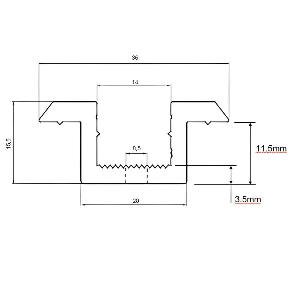
- module gap requirement.
Project
- location;
- wind conditions;
- snow conditions where applicable;
- design code;
- roof or ground mounting;
- rail span and attachment arrangement where known.
Procurement
- quantity;
- target market;
- finish;
- packaging;
- OEM/private label requirements;
- sample requirement;
- CAD/drawing requirements;
- testing or certification requirements.
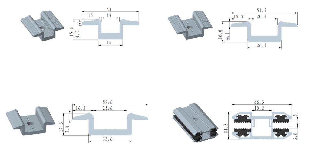
This information allows the supplier to distinguish between:
physical compatibility → engineering qualification → commercial quotation.
That distinction can save significant time later in the procurement process.
16. Common Mid-Clamp Selection Mistakes
Mistake 1: Selecting only by frame height
A nominal frame-height range does not describe the entire frame geometry.
Mistake 2: Assuming physical fit means qualification
A clamp that can physically grip the frame is not automatically approved for the module or project.
Mistake 3: Treating module gap as an arbitrary dimension
The gap is part of the clamp/module interface and should follow the applicable mounting-system requirements.
Mistake 4: Giving one universal torque value
Torque depends on the product and system.
Mistake 5: Evaluating the clamp separately from the rail
The clamp, T-bolt, rail and attachment form a connected load path.
Mistake 6: Using one capacity number for every module
The governing failure mode can change with module frame, clamp geometry, rail and attachment configuration.
Mistake 7: Assuming bonding is automatic
A mechanically suitable clamp is not necessarily a bonding/grounding component.
Mistake 8: Reusing a clamp for a replacement module without checking the frame
A new module may have a different frame geometry or approved mounting zone even when its external dimensions are similar.
17. Product Boundary: What This Guide Does and Does Not Establish
This guide explains the engineering factors that should be considered when evaluating framed-module mid clamps.
It does not establish a universal:
- mid-clamp load rating;
- module frame-height range;
- module gap;
- installation torque;
- rail compatibility;
- bonding capability;
- certification status.
Those values and qualifications must come from the actual product/system documentation or defined engineering evaluation.
For a specific project, the correct sequence is:
Compatibility → Qualification → Project Design
A product can pass the first stage without automatically passing the second or third.
18. Practical Qualification Checklist
Before approving a solar panel mid clamp, check:
- Exact module model identified
- Module frame drawing available
- Approved clamping zone confirmed
- Frame height confirmed
- Frame thickness/profile checked
- Clamp engagement checked on both modules
- Required module gap confirmed
- Rail compatibility confirmed
- T-bolt/fastener compatibility confirmed
- Installation orientation confirmed
- Product-specific torque confirmed
- Bonding/grounding requirements checked separately
- Project loads defined
- Governing failure mode considered
- Applicable certification/listing verified
- Test/calculation evidence checked for configuration and scope
If several of these items are unknown, the product may be suitable for preliminary quotation, but it should not yet be treated as fully qualified for project deployment.
Conclusion
A solar panel mid clamp is a small component with a multi-interface engineering role.
The critical question is not simply whether the clamp can hold a module frame. The relevant connection is:
two module frames → mid clamp → fastener → rail → rail attachment → supporting structure
At the module side, frame geometry, approved clamping zones, engagement and module gap determine whether the physical interface is correct.
At the mounting-system side, the rail and fastener determine how the clamp transfers load into the structure.
At the project level, wind, snow, installation configuration and the governing failure mode determine whether the complete system is adequately qualified.
For this reason, a professional mid-clamp selection process should follow:
Compatibility → Qualification → Project Design
The best supplier qualification is therefore not simply a product catalog or a nominal frame-height range. It is the ability to connect the actual module, clamp, rail and project requirements into a traceable engineering decision.
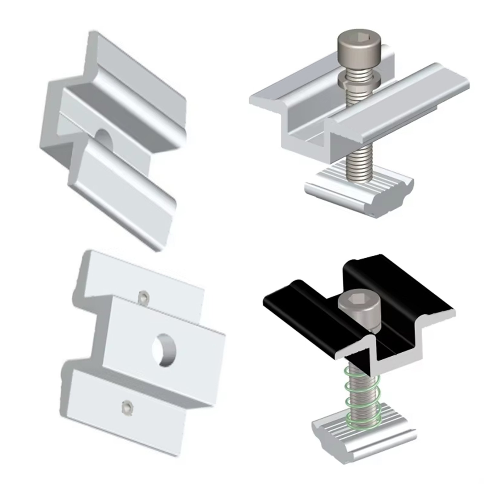
Have a specific module model or frame drawing?
Send us the module details, rail information and project requirements. We can check the mid-clamp interface before quotation or sample development.