
Solar Panel End Clamp: Engineering Guide to Module Compatibility, Clamping, Load and Installation
A solar panel end clamp should be selected from the module frame, approved clamping zone, clamp geometry, rail interface and project loading requirements—not simply from the nominal module frame height.
An end clamp is part of a connected structural interface:
PV module frame → end clamp → rail → rail attachment → roof / ground structure
The clamp may fit the module physically but still be unsuitable for the intended installation if the frame geometry, clamping position, rail interface or installation configuration is not qualified.
A practical selection sequence is:
Module → Clamping Zone → Clamp Geometry → Rail → Load Path → Installation → Evidence
The key distinction is:
Physical fit is not the same as structural qualification, and clamp capacity is not the same as complete PV-system capacity.
1. What Does a Solar Panel End Clamp Do?
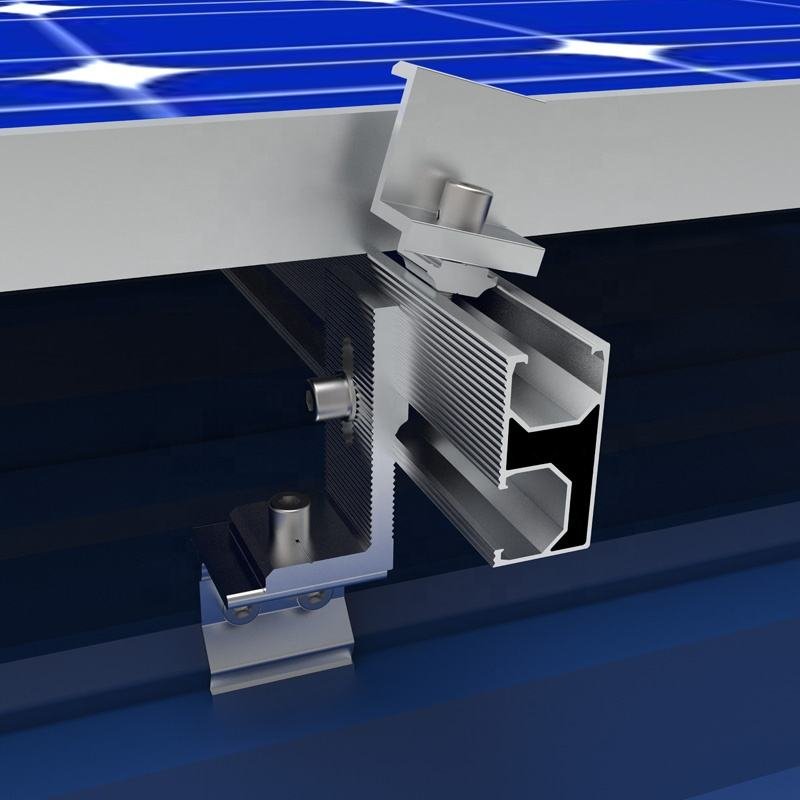
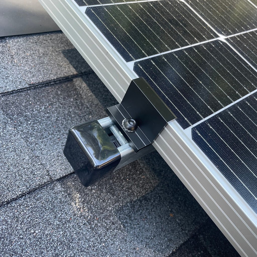
An end clamp secures the outside edge of a framed PV module to a mounting rail.
In a typical rail-mounted system, the load path is:
Module frame → end clamp → rail → rail attachment → roof / ground structure
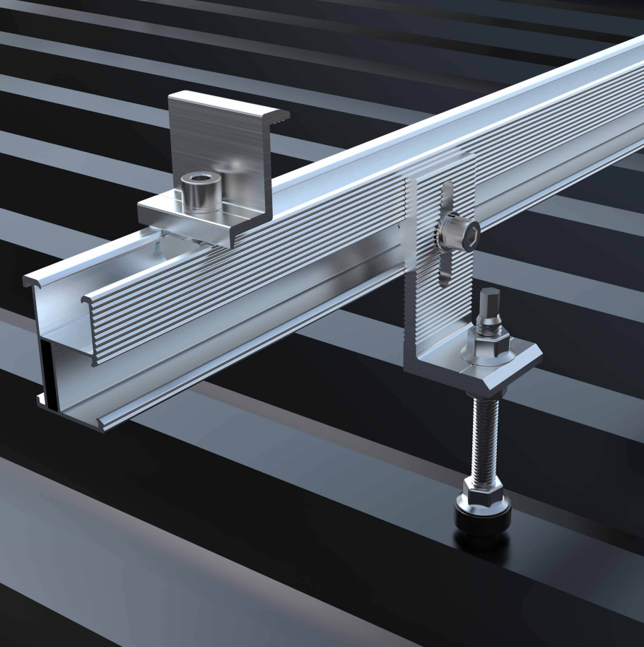
The end clamp therefore forms an interface between the module frame and the mounting rail.
Its performance depends on several connected interfaces:
- module frame;
- clamp body;
- clamp engagement geometry;
- T-bolt, nut or other rail fastener;
- rail channel;
- rail;
- rail-to-structure attachment;
- module manufacturer’s approved clamping zone;
- installation configuration.
This is why an end clamp should not be evaluated only by its material or external dimensions.
2. Start With the Module, Not the Clamp
The first question when selecting an end clamp should be:
What exact module will be installed?
The module manufacturer and model should be identified before final clamp selection.
Useful information includes:
- module manufacturer;
- module model;
- module dimensions;
- frame height;
- frame thickness;
- frame return-flange geometry;
- frame profile;
- approved clamping zone;
- module mechanical-load requirements;
- installation manual.
A module’s wattage or overall dimensions are not enough to establish end-clamp compatibility.
Two modules with the same nominal frame height can have different frame geometry and different approved mounting conditions.
3. Frame Height Is Important, But It Is Not the Whole Compatibility Check
End clamps are often marketed by a frame-height range.
For example, a product may be described as suitable for a particular range of module frame heights.
That information is useful, but it should not automatically be interpreted as structural qualification for every module within that range.
Compatibility can also depend on:
- frame thickness;
- return-flange length;
- frame profile;
- clamp engagement;
- clamp overlap;
- approved clamping zone;
- rail geometry;
- T-bolt or fastening interface.
Therefore:
A frame-height range is a dimensional starting point, not a universal structural approval.
If a customer asks:
“Can your 30–40 mm end clamp fit my module?”
the correct next step is to request the module model or frame drawing rather than simply answering “yes.”
4. The Module Manufacturer’s Clamping Zone Matters
One of the most important pieces of information is the module manufacturer’s approved clamping zone.
The manufacturer may define where the module frame can be supported or clamped for a specified mechanical-load condition.
This means that the following two statements are not equivalent:
“The clamp physically reaches the frame.” and “The module manufacturer allows the module to be clamped at this position.”
The second question is the one that matters for engineering qualification. Clamp position can affect the mechanical behavior of the module frame and the loads that the module can withstand. Therefore, the module installation manual should be checked before finalizing the end-clamp position.
5. Clamp Engagement and Overlap Matter
The end clamp must engage the module frame correctly.
Important interface variables can include:
- clamp height;
- engagement depth;
- overlap with the frame;
- contact geometry;
- clamp position;
- frame thickness;
- return-flange geometry.
Insufficient engagement may reduce the effectiveness of the module-clamp interface.
Incorrect engagement can also create local loading conditions that were not intended by the module manufacturer.
For this reason, a CAD drawing is useful for checking physical interfaces.
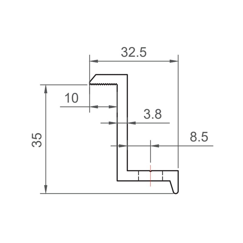
However:
A CAD drawing can establish dimensional compatibility; it does not by itself establish structural capacity.
Structural qualification still requires appropriate evidence for the defined assembly.
6. Physical Fit Does Not Mean Engineering Qualification
This is one of the most important principles for end-clamp selection.
A clamp may:
- slide onto the rail;
- reach the module frame;
- match the nominal frame height;
- appear mechanically secure.
But that does not automatically prove that the installation is structurally qualified.
A proper qualification has at least three layers:
Question | What it establishes |
Does it physically fit? | Dimensional compatibility |
Is the module allowed to be clamped this way? | Module-side qualification |
Is the complete assembly adequate for the project loads? | Structural qualification |
These should not be collapsed into one question. The practical sequence is:
Compatibility → Qualification → Project Design
ICC-ES Reports Ensure Structural Integrity of Solar Panel Installations
7. The End Clamp Is Part of a Load Path
When structural loads act on a PV module, they do not stop at the clamp.
A simplified load path is:
PV module → module frame → end clamp → rail → rail connection → roof/ground attachment → supporting structure
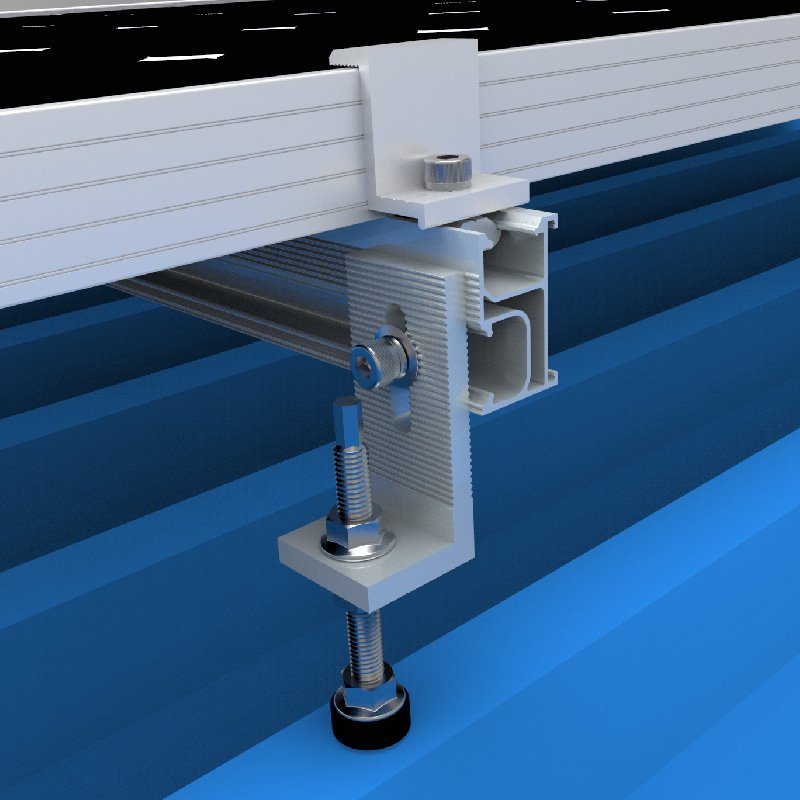
Depending on the system, the governing limit may involve:
- module frame deformation;
- clamp deformation;
- clamp slip;
- clamp-to-frame interface;
- T-bolt/nut interface;
- rail channel;
- rail deformation;
- rail-to-roof attachment;
- roof/substrate;
- installation position;
- module clamping zone.
Therefore:
A strong end clamp does not compensate for an inadequate rail or roof attachment.
Likewise, the capacity of the clamp alone does not establish the allowable capacity of the complete PV mounting system.
8. How Much Load Can a Solar End Clamp Take?
There is no universal end-clamp capacity independent of the module, clamp geometry, rail, fastening configuration and installation conditions.
A useful structural evaluation should consider the complete assembly.
Relevant variables can include:
- module frame geometry;
- clamp geometry;
- clamp engagement;
- clamping position;
- rail type;
- T-bolt/nut interface;
- rail span;
- attachment spacing;
- roof or ground attachment;
- project wind and snow loads;
- load direction;
- installation configuration.
A published product load value should therefore be treated according to its documented scope.
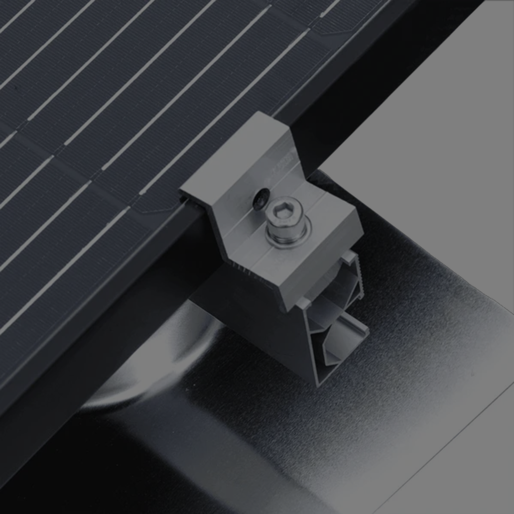
For example:
A load result obtained from a defined module-frame, clamp, rail and installation configuration should not automatically be transferred to a different module or rail.
This is the same reason that material strength alone cannot establish connection capacity.
9. The Module Frame Can Govern
It is easy to focus on whether the aluminum end clamp itself bends or breaks.
That is only one possible failure mode.
The module frame can also be the governing component.
Potential concerns include:
- local frame deformation;
- local damage at the clamping interface;
- inadequate frame engagement;
- module slip;
- loading outside the approved clamping zone.
The clamp can remain apparently intact while the module-side interface becomes the limiting condition.
This leads to an important engineering principle:
The strongest-looking component is not necessarily the governing component.
The relevant question is where the load path reaches its governing limit state.
10. Can a Module Slip Out of the End Clamp?
Module retention depends on the complete interface.
Important variables include:
- clamp geometry;
- frame geometry;
- engagement;
- clamping position;
- fastening;
- rail interface;
- installation quality;
- applied load.
A clamp should not be judged only by whether it appears to cover the module frame.
The actual concern is whether the defined installation maintains the required mechanical engagement under the applicable loading conditions.
This is also why installation instructions and module mounting requirements matter.
11. What Torque Should Be Used?
There is no universal torque value for all solar end clamps.
Torque is product- and system-specific.
It can depend on:
- clamp design;
- bolt/nut system;
- T-bolt geometry;
- rail;
- hardware;
- bonding requirements;
- manufacturer’s installation procedure.
Different mounting systems specify different torque requirements.
Therefore, a generic statement such as:
“Solar end clamps should always be tightened to X Nm”
should not be used without product-specific evidence.
The correct approach is:
Use the torque specified for the exact clamp, hardware and mounting system.
12. Over-Torque Is Not a Substitute for Secure Clamping
More tightening does not automatically mean better retention.
Excessive torque can create installation risks and may affect:
- hardware;
- rail;
- clamp;
- module frame;
- alignment;
- bonding components where applicable.
The objective is to achieve the manufacturer’s specified installation condition—not simply the highest possible tightening force.
Likewise, under-tightening can fail to establish the intended connection condition.
Installation instructions therefore form part of the engineering boundary of the product.
13. The Rail Interface Also Matters
The end clamp does not connect directly to the building structure.
It normally connects to the mounting rail through a T-bolt, nut or another fastening arrangement.
The rail interface can therefore affect the overall load path.
Relevant considerations include:
- rail channel geometry;
- T-bolt compatibility;
- bolt engagement;
- nut engagement;
- clamp orientation;
- rail dimensions;
- rail strength;
- rail span;
- rail-to-structure attachment.
A clamp that physically fits one rail should not automatically be assumed to have the same structural qualification on another rail.
This is another example of:
Physical compatibility ≠ structural equivalence.
14. End Clamp and Module Certification Are Not the Same Thing
Several certification and testing concepts can appear in an end-clamp discussion.
They should be kept separate.
UL 2703
UL 2703 is relevant to PV mounting systems and can cover mounting devices, clamping/retention devices and related functions.
However:
“UL 2703 compliant” is not, by itself, a universal mechanical capacity statement for an end clamp.
The actual listing and its scope should be reviewed.
Depending on the certification, the scope may relate to mechanical loading, grounding/bonding, fire classification, specific modules, module frames or mounting systems.
IEC 61215
IEC 61215 (IEC 61215-1 & IEC 61215-2) is a PV module qualification framework.
It includes mechanical-load testing as part of the module qualification framework.
However:
IEC 61215 is not a universal end-clamp capacity standard.
A module’s IEC 61215 qualification therefore does not automatically qualify every third-party end clamp used with that module.
15. Mechanical Clamping and Bonding Are Different Questions
Some end-clamp systems are designed to provide electrical bonding or grounding functionality.
That can be useful, but mechanical and electrical claims should not be mixed.
There are two separate questions:
Mechanical:
Does the clamp retain the module adequately?
Electrical:
Does the defined clamp/module/rail installation provide the intended bonding or grounding path?
A bonding-capable clamp should therefore be evaluated within its specified:
- module frame;
- rail;
- hardware;
- installation condition;
- certification/listing scope.
A claim that a clamp provides bonding should not automatically be interpreted as proof of mechanical capacity, and vice versa.
16. What Evidence Should Be Requested?
For a technically credible end-clamp qualification, useful evidence should identify the actual configuration.
At minimum, ask for:
Module
- manufacturer;
- model;
- frame drawing;
- frame height;
- frame thickness;
- relevant frame geometry;
- approved clamping zone;
- installation manual.
Clamp
- product/model;
- dimensions;
- material;
- engagement geometry;
- installation instructions.
Rail
- manufacturer/model;
- rail cross-section;
- channel geometry;
- compatible T-bolt/nut;
- installation requirements.
Structural evidence
- test report where available;
- engineering calculation where applicable;
- certification/listing;
- tested module/frame;
- tested rail;
- load direction;
- failure mode;
- installation configuration.
The most useful evidence is evidence that represents the actual proposed assembly.
17. How to Read an End-Clamp Test or Evaluation
A test result should not be reduced to one headline number.
Ask:
1. What module was tested?
A different frame geometry may behave differently.
2. What clamp was tested?
Confirm the exact model and configuration.
3. What rail was used?
The rail is part of the load path.
4. Where was the clamp positioned?
Clamping position can affect module performance.
5. What was the loading direction?
Uplift, downward load and other loading conditions may produce different behavior.
6. What failed?
Possible governing conditions include:
- module frame;
- clamp;
- fastening interface;
- rail;
- another component.
7. What was actually established?
A test result establishes performance of the defined tested configuration.
It does not automatically establish a universal design value for every module and rail.
18. What Information Should Be Included in an End-Clamp RFQ?
A technically useful RFQ should contain more than:
“Please quote 1000 pcs of 35 mm end clamps.”
A better RFQ includes:
Module
- manufacturer;
- model;
- dimensions;
- frame height;
- frame thickness;
- frame drawing;
- approved clamping zone.
Mounting system
- rail manufacturer/model;
- rail cross-section;
- T-bolt/nut;
- intended installation orientation.
Engineering
- project location;
- wind design;
- snow load where applicable;
- roof zone;
- module arrangement;
- required design standard;
- required certification or evaluation.
Product
- clamp material;
- finish;
- visible/hidden design;
- bonding requirement;
- CAD requirement;
- testing requirements.
Procurement
- quantity;
- destination market;
- sample requirement;
- OEM branding;
- packaging;
- delivery requirement.
This information allows the supplier to perform a real compatibility and qualification review rather than simply match a nominal dimension.
19. Common End-Clamp Selection Mistakes
Mistake 1: Selecting only by frame height
Frame height is important, but frame geometry and clamping zone also matter.
Mistake 2: Assuming physical fit means approval
A clamp can physically fit a module without being approved by the module manufacturer.
Mistake 3: Ignoring the module’s clamping zone
The module manufacturer may specify where the frame should be supported or clamped.
Mistake 4: Using a universal torque value
Torque is product/system specific.
Mistake 5: Evaluating the clamp separately from the rail
The rail interface is part of the structural load path.
Mistake 6: Treating UL 2703 as a universal capacity rating
The actual listing and scope must be checked.
Mistake 7: Treating IEC 61215 as clamp certification
IEC 61215 is a module qualification framework.
Mistake 8: Assuming stronger aluminum means stronger system capacity
Material strength does not automatically establish installed connection capacity.
Mistake 9: Treating one published load value as transferable
A result for one module/rail/configuration should not automatically be applied to another.
20. When a Standard End Clamp Is Not Enough
A standard end clamp may require further evaluation when:
- the module frame is unusual;
- the frame geometry falls outside the documented range;
- the module manufacturer specifies a restricted clamping zone;
- the rail is non-standard;
- the required bonding method is unusual;
- project wind loads are high;
- certification requirements are specific to a jurisdiction;
- available test evidence does not represent the proposed assembly;
- the customer requires OEM/custom geometry.
In these situations, the correct response may be:
- a different standard clamp;
- a modified clamp;
- a different rail interface;
- project-specific testing;
- engineering calculation;
- manufacturer approval;
- or a combination of these.
The objective should be to qualify the actual interface rather than force a nominally compatible component into the application.
21. How to Specify an End Clamp Correctly
A technically useful specification should not simply state:
35 mm aluminum end clamp
A better specification identifies the complete interface:
Module model + frame geometry + approved clamping zone + end-clamp geometry + engagement + rail model/interface + hardware + installation requirements + project loading + required evidence
This provides a traceable boundary around the component.
It also makes later RFQ, sample and engineering review much more efficient.
22. Engineering Takeaway
The key question is not:
“Does this end clamp fit my solar panel?”
The better question is:
“Is this end clamp qualified for this module frame, clamping position, rail interface and project loading condition?”
The practical selection sequence is:
Module model → frame geometry → approved clamping zone → clamp engagement → rail interface → load path → installation → evidence → project design
And the engineering boundary should remain clear:
End-clamp capacity is not module capacity, rail capacity, roof-attachment capacity or complete PV-system capacity.
A professional end-clamp selection therefore begins with the module manufacturer’s requirements and ends with qualification of the complete relevant mounting configuration.