
Trapezoidal Metal Roof Clamp: Engineering Guide to Roof Profile, Fastener, Load and Waterproofing
A trapezoidal metal roof clamp should not be selected simply because a roof is described as “trapezoidal.”
The engineering question is whether the specific roof profile, sheet construction, fastener arrangement, attachment location, substrate and project loads form a qualified load path.
For a typical PV installation, the load path may be:
PV module → module clamp → rail / roof attachment → metal roof sheet → fastener → purlin, deck or substrate → building structure
Depending on the attachment design, some systems rely primarily on the roof sheet, while others transfer load through the sheet and fasteners into a purlin, deck or other structural member.
These are different structural systems and should not be treated as interchangeable.
The practical selection sequence is therefore:
Profile → Attachment configuration → Fastener → Load path → Waterproofing → Evidence → Project design
A physical fit is only the beginning. It does not by itself establish structural qualification.
1. What Is a Trapezoidal Metal Roof Clamp?
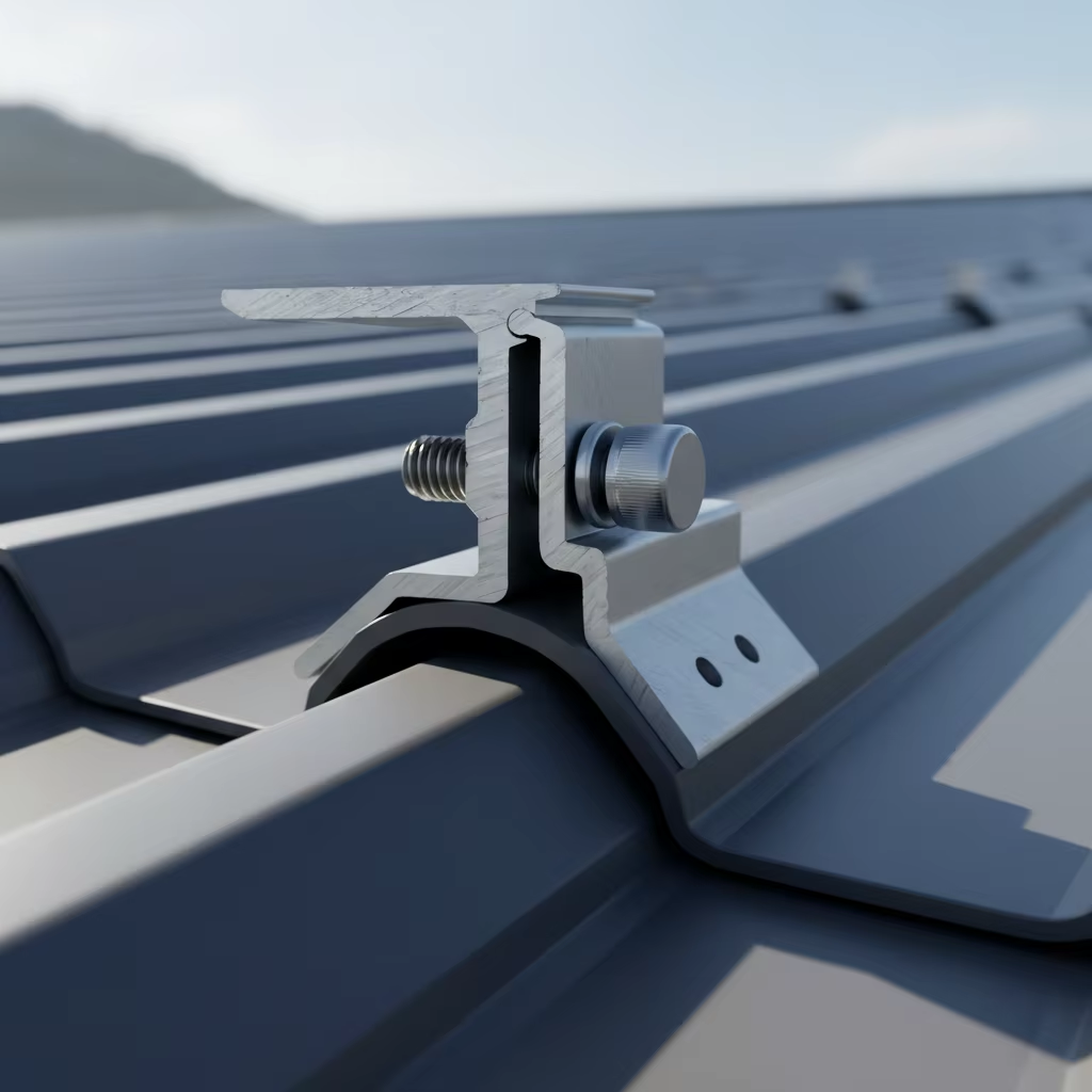
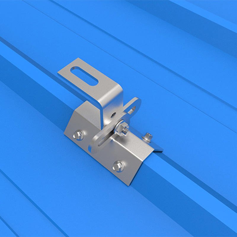
A trapezoidal metal roof clamp or bracket is used to connect a PV mounting system to an exposed-fastened or ribbed metal roof.
Depending on the product and roof construction, the attachment may be:
- mounted on the crest or rib;
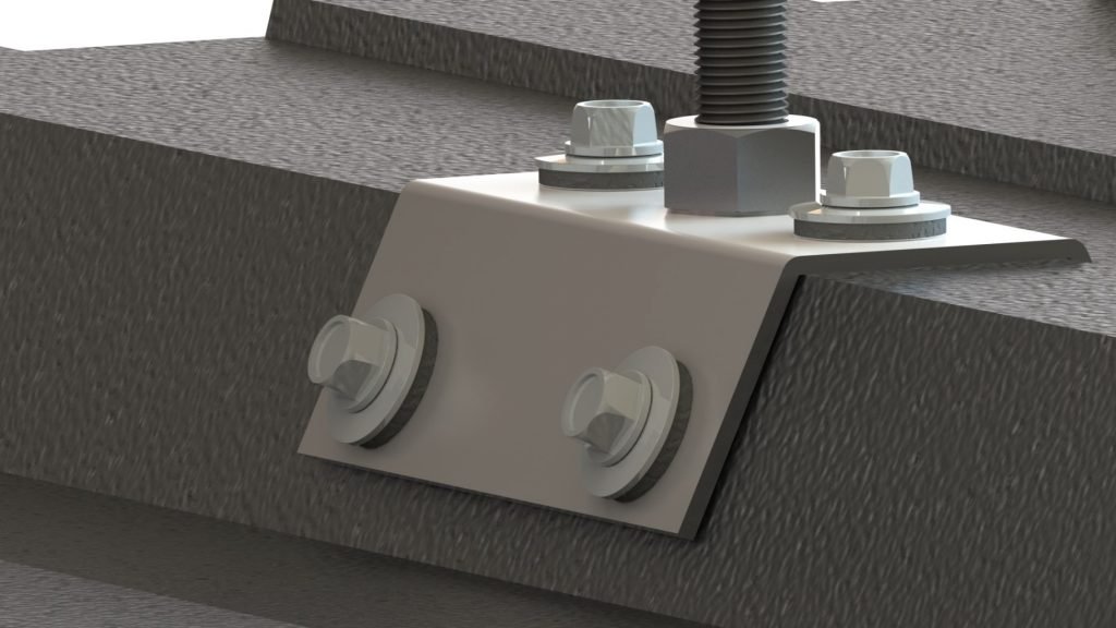
- fixed through the roof sheet;
- sheet-only;
- fixed through the sheet into a deck;
- fixed through the sheet into a purlin or other structural member;
- connected directly to a rail;
- connected to a bracket that then supports the rail.
The term “trapezoidal metal roof” describes a family of roof profiles, not one standardized structural condition.
Two roofs can both be called trapezoidal while having different:
- rib height;
- rib width;
- crest width;
- rib angle;
- valley width;
- rib spacing;
- sheet thickness;
- steel or aluminum construction;
- coating;
- support spacing;
- fastener arrangement.
Those differences can materially change how a PV attachment behaves.
2. Start With the Roof Profile, Not the Clamp
The first question should not be:
“Which clamp do you sell?”
It should be:
“What is the actual roof profile and how is it constructed?”
At minimum, profile verification should consider:
| Roof information | Why it matters |
|---|---|
| Manufacturer / profile model | Identifies the actual roof geometry |
| Rib height | Determines attachment geometry and fastener position |
| Crest width | Determines available bearing/contact area |
| Rib angle | Can affect bracket fit and contact |
| Valley width | Helps distinguish profiles and attachment positions |
| Rib spacing | Affects attachment layout |
| Sheet thickness | Affects local sheet resistance |
| Material | Steel and aluminum should not be treated as structurally interchangeable |
| Coating | Relevant to durability and material compatibility |
| Roof slope | Relevant to load direction and drainage |
| Roof photographs/drawings | Helps verify the actual profile |
A photograph can be useful for initial identification, but a profile drawing or manufacturer information is preferable where structural qualification is required.
“Trapezoidal” is not enough information
A supplier should be cautious if a customer provides only:
Trapezoidal metal roof, 0.8 mm sheet.
That information may still be insufficient.
The actual rib geometry, material, fastener arrangement, support condition and intended attachment method can all affect the engineering result.
This is why a qualified RFQ should begin with the actual roof profile.
3. Understand the Load Path Before Looking at Capacity
A trapezoidal roof attachment is part of a chain, not an isolated component.
A typical sheet-attached system can be represented as:
PV module → module clamp → rail → roof bracket → fastener → metal sheet → supporting structure
Another configuration may be:
PV module → module clamp → rail → bracket → fastener → purlin/deck → building structure
The governing failure mode can occur at any point in this chain.
For example:
- bracket deformation;
- fastener pull-out;
- sheet pull-through;
- sheet tearing;
- rib or crest deformation;
- fastener shear;
- rail/bracket connection failure;
- substrate failure;
- installation-induced damage;
- waterproofing failure;
- corrosion.
Therefore:
A stronger clamp does not automatically produce a stronger roof attachment.
Likewise, a fastener with a high nominal tensile strength does not automatically mean that the installed roof connection has the same resistance. The roof sheet and its supporting structure remain part of the connection.
4. Sheet-Only and Structure-Attached Systems Are Different
One of the most important distinctions in trapezoidal roof mounting is whether the attachment relies primarily on the roof sheet or transfers load into the structural support.
Sheet-only attachment
A simplified load path is: Bracket → fastener → roof sheet → roof system
The sheet and fastener arrangement therefore become critical structural elements.
The relevant failure modes can include:
- fastener pull-out;
- sheet pull-through;
- sheet tearing;
- local rib deformation;
- fastener shear;
- fatigue or cyclic deterioration.
Structure-attached configuration
A different load path may be: Bracket → fastener → sheet → purlin/deck → structure
or, depending on the attachment: Bracket / fastener → structural member
In these systems, the capacity of the supporting member becomes part of the engineering assessment.
The important point is not that one approach is universally better.
The important point is: They are different load paths and require different qualification.
A sheet-only test should not automatically be presented as evidence for a structurally attached configuration, and vice versa.
5. What Actually Governs Trapezoidal Roof Attachment Capacity?
There is no universal load capacity for a trapezoidal metal roof clamp.
The result depends on the defined assembly.
Important variables include:
5.1 Roof profile
Rib geometry determines how the bracket contacts the roof and where the fastener can be installed.
A bracket that physically fits one profile may not provide the same mechanical behavior on another profile.
5.2 Sheet material
Steel and aluminum should not be treated as structurally interchangeable.
Their mechanical behavior, thickness, local deformation and fastener interaction can differ.
5.3 Sheet thickness
Thickness is an engineering input, but thickness alone does not determine capacity.
A statement such as:
“This clamp is suitable for 0.8 mm sheet”
does not establish a universal structural capacity unless the relevant roof profile, material, fastener configuration, loading and evidence are also defined.
5.4 Fastener
Fastener performance depends on more than nominal diameter.
Relevant variables include:
- fastener type;
- diameter;
- thread geometry;
- length;
- embedment;
- substrate;
- washer/head geometry;
- coating/material;
- installation condition.
A larger screw does not automatically provide proportionally greater connection resistance.
5.5 Fastener quantity
The number of fasteners can be part of the tested assembly.
For example, evidence for a four-fastener bracket should not automatically be interpreted as evidence for a two-fastener installation.
The installation configuration matters.
5.6 Load direction
Roof attachments can experience:
- wind uplift;
- downward loading;
- shear parallel to the roof;
- shear perpendicular to the roof;
- combinations of these actions.
Resistance can differ with load direction.
Therefore, a single load-to-failure number without a clearly defined loading direction is of limited engineering value.
5.7 Supporting structure
For structure-attached systems, purlin, deck or other substrate properties become part of the load path.
The attachment cannot be qualified independently from the structure it relies on.
6. Pull-Out and Pull-Through Are Different Failure Modes
Two terms frequently appear in metal-roof attachment discussions: pull-out and pull-through. They should not be treated as the same thing.
Fastener pull-out
Pull-out concerns withdrawal of the fastener from the material into which it is installed.
Resistance depends on factors such as:
- fastener geometry;
- diameter;
- thread;
- substrate;
- effective embedment;
- material properties;
- installation condition;
- load direction.
Sheet pull-through
Pull-through can occur when the roof sheet fails around the fastener or washer while the fastener itself remains intact.
The relevant variables can include:
- sheet thickness;
- material;
- fastener/washer geometry;
- fastener location;
- load direction;
- support condition;
- local sheet geometry.
These are different failure mechanisms.
A screw specification therefore cannot by itself establish the resistance of the complete roof attachment.
7. Rib and Crest Geometry Affect Clamp Selection
The attachment interface must provide adequate mechanical contact with the actual roof profile.
Important geometric considerations include:
- rib height;
- rib width;
- crest width;
- rib angle;
- available bearing area;
- fastener access;
- sealing surface;
- bracket contact geometry.
A profile may appear visually similar to another roof while still being unsuitable for the same attachment geometry.
This is particularly important for products intended to fit multiple trapezoidal profiles.
A useful distinction is:
Profile compatibility is not the same as structural equivalence.
If a bracket is claimed to work on several profiles, the supplier should be able to explain the applicable geometry and, where relevant, the evidence supporting those configurations.
8. High-Rib and Low-Rib Attachment Is Not Just a Product Choice
The location of the attachment relative to the roof profile affects the mechanical arrangement.
High-rib and low-rib configurations can create different:
- fastener positions;
- contact conditions;
- sealing details;
- load directions;
- local sheet behavior;
- bracket geometry.
The correct configuration depends on the actual roof system and attachment design.
It should not be assumed that a bracket designed for one rib location can simply be moved to another location without qualification.
9. Wind Uplift Is Usually a Connection-Chain Problem
Customers often ask:
“How much wind uplift can this clamp take?”
The useful engineering answer is not simply a number.
Wind demand must first be established for the project, including relevant factors such as:
- location;
- applicable design standard;
- building geometry;
- roof zone;
- module arrangement;
- attachment spacing;
- tributary area;
- load direction.
The resulting demand is then transferred through the mounting system:
PV module → module clamp → rail → roof attachment → fastener → roof sheet → purlin/deck/structure
The governing resistance may be:
- the bracket;
- the fastener;
- the roof sheet;
- the supporting structure;
- or another component in the load path.
Therefore:
Clamp capacity alone does not determine the allowable PV array size or attachment spacing.
Attachment spacing should be established from the project load and the qualified resistance of the complete relevant load path.
10. Fastener Orientation Can Change the Connection Behavior
Bracket geometry can influence whether fasteners primarily experience withdrawal, shear, or a combination.
This is one reason that two visually similar roof brackets can behave differently.
Some commercial bracket designs deliberately use geometry intended to place fastener forces more into shear rather than direct withdrawal. Such manufacturer-specific design claims should be treated as evidence for the documented configuration rather than as a universal principle applicable to every bracket.
For a project qualification, the relevant questions are:
- What is the bracket geometry?
- Where are the fasteners located?
- How are the fastener forces transferred?
- What roof material and thickness were evaluated?
- What load direction was tested?
- What failure mode governed?
11. Waterproofing Is Part of the Attachment System
A roof attachment has two separate engineering responsibilities: Structural connection and weather resistance.
A common mistake is to treat waterproofing as equivalent to:
“The product has EPDM.”
EPDM, butyl or sealant can be an important part of the weathering detail, but the complete waterproofing performance depends on the attachment assembly.
Relevant factors include:
- fastener;
- washer;
- EPDM/butyl/sealing element;
- bracket base;
- penetration location;
- roof drainage plane;
- roof slope;
- installation position;
- compression;
- installation damage.
The sealing component must remain correctly positioned and installed.
Therefore:
EPDM or sealant is part of a waterproofing detail; it is not, by itself, proof of long-term roof weather resistance.
For penetrated roof systems, the location of the penetration relative to the drainage path is also important.
12. Installation Quality Can Affect Structural and Waterproofing Performance
The same hardware can perform differently if installed incorrectly.
Relevant installation factors can include:
- correct bracket position;
- correct fastener location;
- correct fastener quantity;
- correct washer/sealing arrangement;
- correct installation torque where specified;
- avoidance of over-tightening;
- avoiding damage to the roof sheet;
- maintaining the required contact geometry.
Over-tightening can damage components or the roof.
Under-tightening can reduce the intended engagement or sealing condition.
Where a manufacturer’s tested installation configuration specifies a particular fastener quantity or installation arrangement, changing that configuration should not automatically be treated as equivalent.
13. Existing Roof Screws Should Not Automatically Be Reused
A common practical question is:
“Can we use the existing metal-roof screws to mount the solar system?”
The existence of an installed roof screw does not establish that it is suitable for the PV attachment.
The existing screw is part of the original roof system and may have been selected for a different purpose and loading condition.
Before relying on existing fasteners, the engineering review should consider:
- fastener type;
- diameter;
- length;
- thread;
- substrate;
- embedment;
- washer;
- roof sheet;
- existing spacing;
- corrosion condition;
- original design;
- new PV load;
- load direction.
If these conditions cannot be verified, the existing fastener should not simply be assumed to be an acceptable PV attachment.
14. What Evidence Should a Trapezoidal Roof Clamp Supplier Provide?
For a technically credible product, a useful evidence package should describe the tested or qualified configuration rather than simply provide a maximum load number.
At minimum, ask:
Roof
- profile/model;
- profile drawing;
- rib dimensions;
- material;
- sheet thickness;
- coating;
- roof slope.
Attachment
- clamp/bracket model;
- bracket dimensions;
- contact geometry;
- attachment location;
- sheet-only or structural attachment.
Fastener
- type;
- diameter;
- length;
- material/coating;
- washer;
- quantity;
- installation configuration.
Structure
- purlin/deck/substrate;
- thickness;
- spacing;
- relevant support conditions.
Test
- test method;
- loading direction;
- specimen configuration;
- support condition;
- failure mode;
- maximum/test load;
- whether the result is ultimate test data or a design value.
The closer the tested configuration is to the actual project, the more useful the evidence becomes.
15. Test Load Is Not Automatically Project Design Resistance
This distinction is critical.
It does not automatically establish the design resistance for every project.
A proper engineering interpretation may need to consider:
- test configuration;
- variability;
- failure mode;
- applicable design method;
- safety or reduction factors;
- load combinations;
- project conditions;
- applicability of the tested assembly to the proposed installation.
For example:
A test performed on one profile, sheet thickness, fastener arrangement and loading direction should not automatically be presented as a universal capacity for all trapezoidal roofs.
The evidence should remain bounded by what was actually tested.
16. How to Evaluate a Trapezoidal Roof Clamp Before Ordering
A practical qualification process is:
Step 1 — Identify the roof
Obtain the manufacturer/profile and preferably a profile drawing.
Step 2 — Confirm construction
Determine:
- material;
- sheet thickness;
- roof slope;
- purlin/deck arrangement;
- existing fasteners.
Step 3 — Define the attachment
Confirm:
- top-fix or bottom-fix;
- sheet-only or structure-attached;
- crest/rib location;
- bracket geometry;
- rail interface.
Step 4 — Define the fastener
Confirm the exact:
- type;
- size;
- quantity;
- washer;
- substrate;
- installation condition.
Step 5 — Establish project loads
Provide the relevant:
- project location;
- wind design;
- snow design where applicable;
- roof zone;
- module arrangement;
- attachment spacing;
- applicable design code.
Step 6 — Identify the governing failure mode
Review the complete connection chain rather than only the bracket.
Step 7 — Check waterproofing
Verify the penetration and sealing detail separately from structural capacity.
Step 8 — Compare evidence with the actual configuration
Ask whether the available test, calculation or manufacturer’s documentation actually applies to the proposed roof and attachment.
17. What Information Should Be Included in an RFQ?
A qualified quotation request should contain enough information for the supplier to determine whether the proposed attachment is actually suitable.
Roof information
- Roof manufacturer
- Profile/model
- Profile drawing if available
- Rib height
- Rib top/crest width
- Rib angle
- Valley width
- Sheet thickness
- Steel or aluminum
- Coating
- Roof slope
- Roof photographs
Existing structure
- Purlin material and thickness
- Purlin spacing
- Deck type/thickness where applicable
- Existing fastener type and spacing
- Substrate information
PV system
- Module manufacturer/model
- Module dimensions
- Frame height
- Module orientation
- Rail manufacturer/model
- Rail span
- Proposed attachment spacing
Engineering
- Project location
- Wind load/design basis
- Snow load where applicable
- Roof zone
- Applicable design code
- Required safety factors
- Seismic requirements where relevant
Product and procurement
- Sheet-only or structure-attached
- Top-fix or bottom-fix
- Fastener specification
- Material and finish
- Quantity
- Sample requirement
- CAD requirement
- Testing/documentation requirements
- OEM/custom requirements
- Destination market
This information allows a supplier to move from a generic product quotation toward an actual engineering qualification.
18. Common Mistakes
Mistake 1: Selecting by the word “trapezoidal”
A roof category is not enough to establish compatibility.
Mistake 2: Using sheet thickness as the only structural input
Thickness matters, but profile, material, fastener, support and load direction also matter.
Mistake 3: Using screw strength as connection capacity
Fastener nominal strength is not the same as installed roof attachment resistance.
Mistake 4: Treating pull-out and pull-through as the same
They represent different failure mechanisms.
Mistake 5: Assuming more screws always means proportionally more capacity
Fastener quantity and spacing are part of the connection configuration and may have nonlinear or configuration-dependent effects.
Mistake 6: Treating EPDM as a waterproofing guarantee
Weather resistance depends on the complete attachment detail and installation.
Mistake 7: Applying a sheet-only test to a different structural configuration
A different load path requires separate qualification.
Mistake 8: Treating one test result as a universal product rating
Test evidence is bounded by the tested configuration.
Mistake 9: Assuming physical fit means engineering approval
A bracket can physically fit a profile without being structurally qualified for the intended application.
19. The Right Way to Specify a Trapezoidal Metal Roof Clamp
A useful specification should identify the configuration, not merely the product name.
Instead of:
Trapezoidal roof clamp, aluminum, four screws.
A technically useful specification should describe:
Roof profile + sheet material/thickness + attachment location + bracket geometry + fastener + washer/sealing system + fastener quantity + substrate + rail interface + project loads + required evidence.
This creates a traceable engineering boundary around the product.
20. When a Standard Trapezoidal Clamp Is Not Enough
A standard attachment may not be appropriate when:
- the roof profile is unusual;
- the crest/rib geometry is outside the documented range;
- sheet thickness or material differs from the qualified configuration;
- the attachment must connect to a specific structural member;
- the project has unusually high wind demand;
- the roof is subject to demanding environmental exposure;
- the available test evidence does not represent the proposed installation;
- the customer requires project-specific calculations or testing.
In these cases, the appropriate solution may be a modified bracket, profile-specific attachment, structural attachment, additional testing or project-specific engineering evaluation.
The objective should not be to force a standard clamp into an unsuitable application.
21. Product and Engineering Boundary
A trapezoidal metal roof clamp is one component of a larger PV mounting system.
Its engineering boundary should be considered separately from:
- PV module;
- module clamp;
- rail;
- roof sheet;
- fastener;
- purlin/deck;
- building structure;
- waterproofing system.
The strongest component does not necessarily govern.
The governing condition may occur in the roof sheet, fastener, substrate, bracket, rail connection or another part of the load path.
Therefore:
A qualified trapezoidal roof attachment is a defined roof-and-mounting configuration, not simply a piece of hardware that fits a rib.
22. Engineering Takeaway
The most important questions when selecting a trapezoidal metal roof clamp are not:
“What is the clamp made of?”
“How many screws does it have?”
“What is its maximum load?”
The more useful questions are:
- What is the exact roof profile?
- What material and thickness is the sheet?
- Where does the attachment sit on the profile?
- Is the system sheet-only or structurally attached?
- What fastener and washer configuration is used?
- What is the actual load direction and project demand?
- Which failure mode governs?
- Does the available test or calculation represent the proposed configuration?
- How is the roof penetration sealed and drained?
- What information is required before the attachment can be qualified?
For professional PV mounting, the correct sequence is:
Actual roof profile → attachment geometry → fastener/substrate → load path → failure modes → waterproofing → evidence → project design
That is the basis for selecting a trapezoidal metal roof attachment with engineering confidence.
Evidence Basis
The engineering framework above is based on the project’s evidence registry, including:
- ASTM E1592-25 for structural evaluation of metal roof/siding systems and anchor-to-panel attachments;
- EN 1993-1-3:2024 for cold-formed steel members, sheeting and relevant fastener connection design;
- ASTM E1646 for water penetration of exterior metal roof panel systems;
- documented trapezoidal-roof attachment systems from K2;
- exposed-fastened and ribbed-roof attachment documentation from S-5!;
- technical research concerning pull-through, pull-out, splitting and cyclic behavior of metal roof sheets.
Manufacturer-specific examples are treated as evidence of their documented configurations, not as universal proof for all trapezoidal roof attachments.
Have a specific trapezoidal roof profile?
Send us the roof drawing, sheet specification and project requirements for attachment qualification.